
High-toughness ductile iron cylinder heads for marine diesel engines exhibit unique challenges due to their complex geometry and material solidification characteristics. The mushy solidification mode of ductile iron frequently causes insufficient graphite nodule count, oversized graphite spheres, reduced mechanical properties, and defects like shrinkage cavity casting and gas porosity. Our investigation focuses on eliminating these issues through controlled solidification techniques.
Solidification Challenges in Complex Geometries
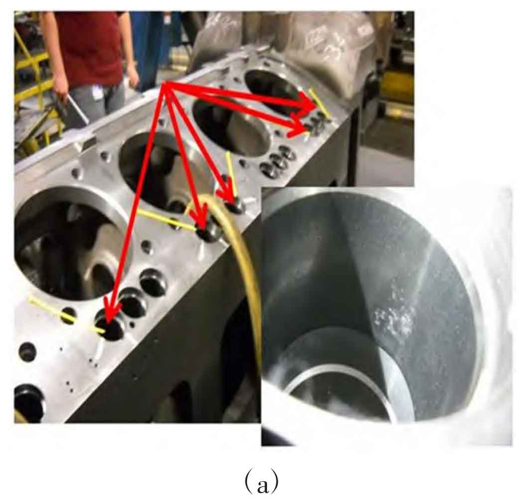
The integrated design featuring intake manifolds and rocker arm seats creates multiple isolated thermal junctions. During solidification, these regions experience insufficient molten metal feeding, leading to shrinkage cavity casting defects. The solidification time differential between sections follows:
$$ t_f = \frac{V}{A} \cdot \frac{\rho L}{k(T_m – T_0)} $$
Where \( t_f \) = local solidification time, \( V/A \) = volume-to-surface ratio (modulus), and \( k \) = thermal conductivity. Higher \( V/A \) ratios at thermal junctions exponentially extend \( t_f \), exceeding the feeding window and causing shrinkage defects.
| Defect Location | Modulus (cm) | Solidification Time (s) | Defect Type |
|---|---|---|---|
| Valve Guide Holes | 1.8 | 310 | Macro-shrinkage |
| Bolt Holes | 1.5 | 260 | Micro-shrinkage |
| Exhaust Manifold | 2.2 | 380 | Shrinkage Porosity |
Shrinkage Cavity Casting Mitigation Strategies
We implemented chilling solutions to accelerate solidification at critical junctions:
- Valve Guide Zones:
- External chills: Ø25mm × 60mm steel chills
- Internal chills: Ø8mm steel inserts
Chill effectiveness calculated via Fourier number:
$$ Fo = \frac{\alpha t}{L^2} $$
Where \( \alpha \) = thermal diffusivity, \( L \) = chill thickness - Bolt Holes: Chromite sand-coated chills (6-8mm coating thickness)
- Intake Manifold: External chills at gating edges
Chromite sand’s thermal properties (Table 2) demonstrate superior heat extraction capabilities essential for shrinkage cavity casting prevention:
| Material | Thermal Conductivity (W/m·K) | Heat Capacity (J/kg·K) | Chilling Efficiency Index* |
|---|---|---|---|
| Chromite Sand | 2.5 | 900 | 1.8 |
| Silica Sand | 1.0 | 750 | 0.7 |
| Graphite | 110 | 710 | 1.2 |
*Higher values indicate better shrinkage cavity casting prevention
Gas Porosity Control Methodology
Gas entrapment from 27 resin-coated cores caused subsurface blowholes. Our solution combined:
$$ G_{total} = G_{resin} \cdot e^{(-E_a/RT)} \cdot V_{core} $$
Where \( G_{total} \) = total gas generation, \( E_a \) = activation energy. We reduced \( G_{total} \) by:
- Implementing 180°C/4h core baking to decompose low-temperature binders
- Designing venting channels with total cross-section:
$$ A_v = 0.03 \cdot A_{casting} $$
Process Verification and Industrial Implementation
After implementing modifications, we achieved:
- 95% yield rate (vs. initial 80%)
- Zero shrinkage cavity casting defects in sectioned components
- Elimination of gas-related scrap
Microstructural analysis confirmed refined graphite nodules (nodule count >150/mm² vs. initial <100/mm²) and reduced nodularity (85-90%) in previous shrinkage cavity casting zones.
Conclusion
Strategic placement of high-efficiency chills combined with optimized core venting eliminates shrinkage cavity casting defects in complex ductile iron castings. The methodology demonstrates particular effectiveness for components with integrated features and restricted feeding paths. Chromite sand’s thermal properties prove critical for shrinkage cavity casting mitigation in thermally isolated regions.