1. Design of pouring system scheme
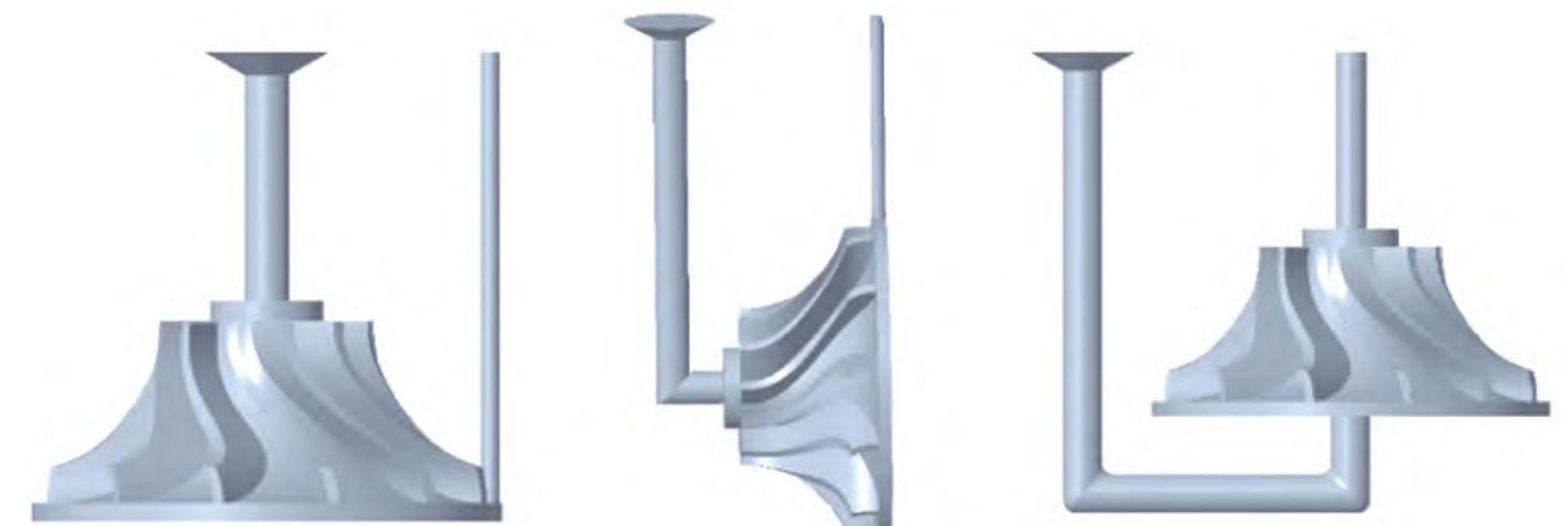
Based on the design principles of component structure and investment casting gating system, three gating system schemes were designed for the impeller gating system, namely one top gating type, one side gating type, and one bottom gating type, as shown in Figure 1.

2. Simulation analysis
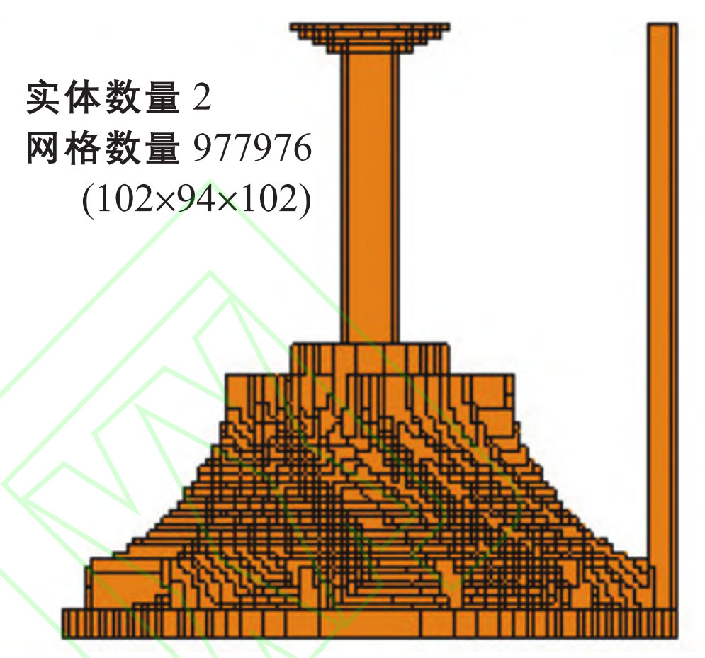
Firstly, import the stl file of the top pouring system into the preprocessing module of Anycasting software for grid partitioning, as shown in Figure 2. The process parameters used for simulation are shown in the table. Process and calculate the pre processing results through the solver module, and then use the post processing module to observe and analyze the results.
| Casting mold | Pouring materials | Pouring temperature/℃ | Preheating temperature of mold shell/℃ | Pouring speed/(cm · s ^ -1) |
| Metal mold | ZL104 | 750 | 650 | 25 |

The simulation process of top pouring is shown in Figure 3 (a) (see electronic version for color image, the same below): The molten aluminum alloy enters the bottom of the mold cavity from the main channel, and under the action of gravity, the flow rate of the melt entering the mold cavity increases, the impact force increases, and turbulence is generated, which leads to unstable filling and may cause defects in the investment casting; In addition, molten metal is sequentially filled into the mold cavity from top to bottom, which may prevent the gas in the cavity from being completely discharged, ultimately leading to shrinkage and porosity on the investment casting. Observe the combined defects (temperature gradient) in Figure 3 (b) × The prediction of interface movement speed (reciprocal) and the shrinkage fraction in Figure 3 (c) show that shrinkage defects are concentrated at the bottom of the investment casting.

The simulation process of side injection casting is shown in Figure 4 (a): the filling process is smooth, and the solidification sequence is from bottom to top. Observing the combined defect prediction diagram in Figure 4 (b) and the shrinkage porosity fraction in Figure 4 (c), it was found that the combined defect of the investment casting occurred at the junction of the flow channel and the investment casting. There may be shrinkage porosity and shrinkage porosity on the flow channel and blade, which may be due to the rapid filling of the mold, making it impossible to fully exhaust the air in the mold cavity.

The simulation process of bottom pouring is shown in Figure 5 (a): the solidification process meets the requirements of sequential solidification. From the combined defect diagram in Figure 5 (b), it can be observed that there are no combined defects on the surface of the investment casting, while in Figure 5 (c), the shrinkage and porosity defects are concentrated at the corner of the flow channel, while there are almost no defects on the surface of the blade.

3. Determine the riser plan for the pouring system
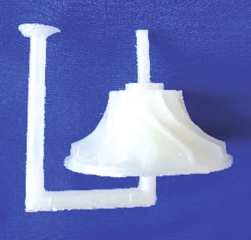
According to the analysis results of the simulated pouring plan, it can be concluded that the defects of the bottom pouring system are concentrated on the flow channel, while the defects of the investment casting itself can be almost ignored. Therefore, the bottom pouring system is selected as the experimental plan. Print out the bottom pouring plan using an FDM (Melt Deposition Manufacturing) 3D printer, as shown in Figure 6.

