
The reliability of fluid control systems is fundamentally dependent on the quality and performance of their constituent valves. As a pivotal category of sand casting products, water valves are frequently produced using the sodium silicate (water glass) sand casting process. This method is favored for its adaptability, relatively low cost, and suitability for small to medium batch production. This article details a comprehensive analysis and design of the casting process for a specific water valve component, aiming to enhance final product quality while optimizing production economics. The focus lies on leveraging process design and numerical simulation to prevent typical defects, ensuring the valve meets stringent performance criteria for sealing and pressure integrity.
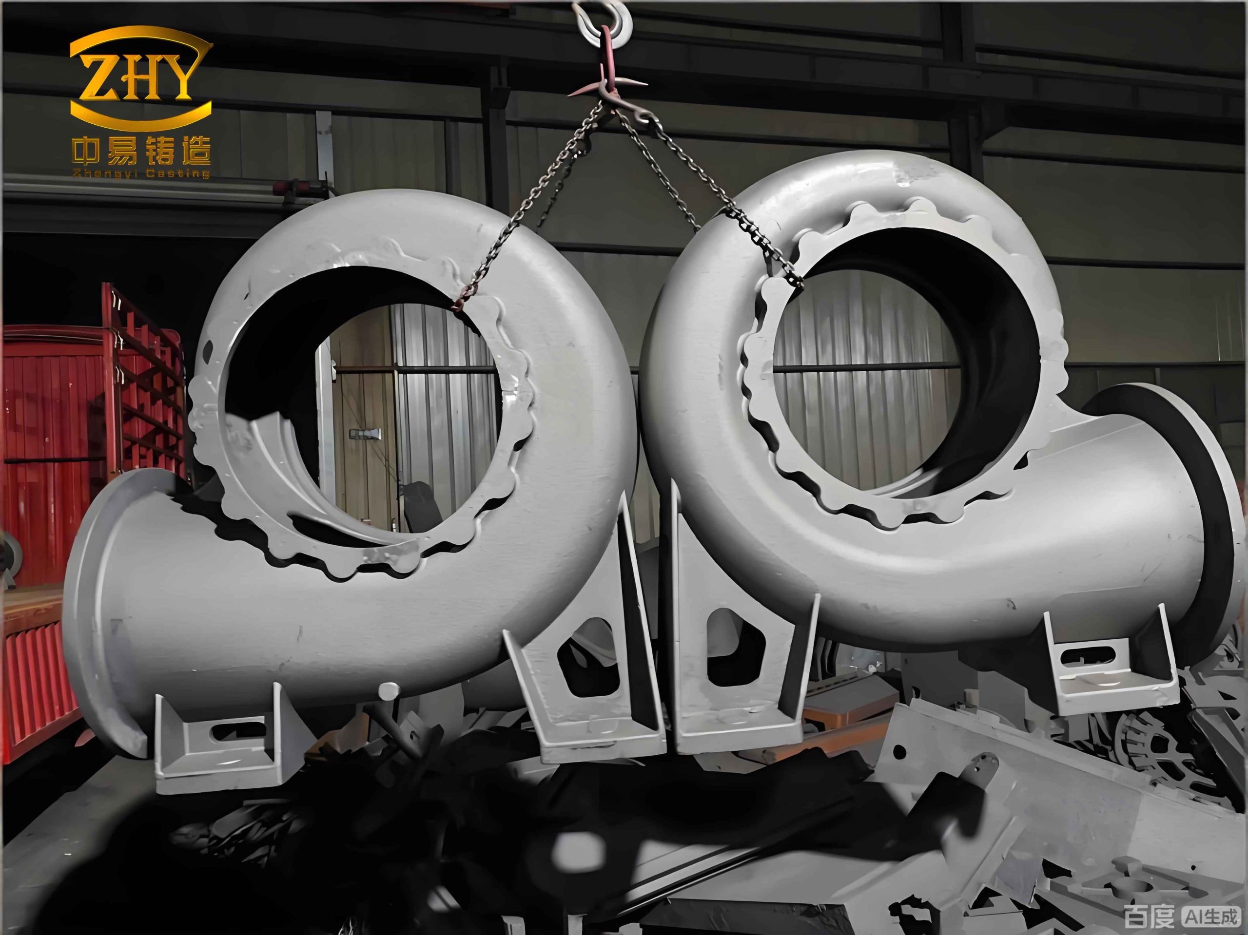
The component in question is a multi-port valve body with an overall envelope dimension of approximately 480 mm x 448 mm x 250 mm. Its internal geometry consists of interconnected flow channels, creating a complex, hollow structure. The design features several critical flanged connection faces and sealing surfaces, which demand high dimensional accuracy and superior surface finish to ensure leak-proof operation under pressure. The specified material is ductile iron (nodular graphite iron), selected over alternatives like aluminum alloys for its superior strength, hardness, excellent pressure resistance, and favorable corrosion resistance—all at a competitive cost point. The casting must be free from detrimental defects such as shrinkage porosity, gas holes, and inclusions, and is required to undergo a stress-relief annealing process post-casting.
The successful production of such sand casting products hinges on a meticulously planned sequence of steps, from mold making to pouring and solidification control. The following sections delve into the core aspects of this engineering endeavor.
1. Foundry Process Design and Rationale
1.1 Selection of Molding Method and Sand Mixture
Given the valve’s size, structural complexity, and the context of small-batch production, the sodium silicate sand casting process was deemed optimal. This green sand process variant offers significant flexibility, operational simplicity for complex shapes, and cost-effectiveness for limited production runs, perfectly aligning with the needs for manufacturing these specific sand casting products.
The mold material is a mixture of high-silica sand (SiO₂ > 95%) and sodium silicate binder, typically with a ratio between 3% to 5% binder by sand weight. A liquid ester hardener or CO₂ gas is used to catalyze the setting reaction. The chemical hardening process can be summarized by the reaction of sodium silicate with CO₂:
$$ Na_2O \cdot nSiO_2 \cdot mH_2O + CO_2 \rightarrow Na_2CO_3 + nSiO_2 \cdot (m-1)H_2O + Heat $$
The precipitated silica gel ($$ nSiO_2 \cdot (m-1)H_2O $$) forms a rigid, three-dimensional network that binds the sand grains, providing the mold with excellent thermal stability and sufficient strength to withstand the static and dynamic pressures of molten metal. Key properties of the sand mixture are outlined below:
| Parameter | Specification / Typical Value | Significance |
|---|---|---|
| Sand Grain Fineness (AFS) | 50 – 70 | Controls surface finish and permeability. |
| Sodium Silicate Addition | 3.5 – 4.5 wt.% | Primary binder; controls mold strength. |
| Ester Hardener Addition | 10-15% of binder weight | Controls workability time and strip time. |
| Mold Hardness (B-scale) | > 85 | Indicates sufficient strength to resist metal pressure. |
| Permeability Number | > 120 | Critical for allowing gases to escape during pouring. |
1.2 Parting Plane Selection and Mold Cavity Layout
A strategic parting plane is essential for moldability, core placement, and ease of casting extraction. Analysis of the valve geometry reveals symmetry about its central horizontal plane. Selecting this plane as the parting line results in a simple two-part mold (cope and drag) with minimal undercuts. This orientation also keeps the mold height manageable and facilitates the positioning of the gating system. The internal flow channels are formed using dry sand cores, which are manufactured from the same sodium silicate sand mixture and inserted into the mold cavity before closing. To maximize yield and productivity, a “one mold, two castings” strategy is adopted, with two valve cavities arranged symmetrically along a common runner system. This approach is economically advantageous for batch production of sand casting products.
1.3 Gating and Feeding System Engineering
The design of the gating and feeding system is paramount for controlling the filling sequence, minimizing turbulence, and ensuring directional solidification to feed shrinkage. For this valve, a pressurized gating system with a ratio is designed to promote rapid and smooth filling. The system consists of:
- Pouring Basin & Sprue: A single sprue is located at the central junction.
- Runner: A primary horizontal runner placed at the parting plane branches into four separate ingates.
- Ingates: Four ingates are positioned to introduce metal into the lower sections of the two valve cavities, ensuring bottom-up filling.
To minimize turbulent entry which can cause mold erosion and air entrainment, the cross-sectional areas are designed to maintain a controlled pressure gradient. A common ratio used is:
$$ A_{sprue} : \Sigma A_{runner} : \Sigma A_{ingate} = 1 : 1.2 : 1.5 $$
Where \( A \) represents the cross-sectional area. The initial filling velocity \( v \) at the ingate can be estimated using Bernoulli’s principle, simplified for the system:
$$ v = C_d \sqrt{2gh} $$
Here, \( C_d \) is the discharge coefficient (≈0.8 for sand molds), \( g \) is gravity, and \( h \) is the effective metallostatic head. For a head of ~300 mm, the initial velocity is approximately:
$$ v \approx 0.8 \times \sqrt{2 \times 9.81 \times 0.3} \approx 1.95 \text{ m/s} $$
A Reynolds Number \( Re \) check for the ingate confirms flow characteristics:
$$ Re = \frac{\rho v D_h}{\mu} $$
For ductile iron ($$ \rho \approx 7000 \text{ kg/m}^3 $$, $$ \mu \approx 5.5 \times 10^{-3} \text{ Pa·s} $$) and a hydraulic diameter \( D_h \) of 20 mm, \( Re \approx 50,000 \), indicating turbulent flow, which is typical and manageable with proper gating design to minimize splashing.
Solidification feeding is addressed using Chvorinov’s Rule to identify thermal centers. The solidification time \( t_s \) for a section is proportional to the square of its volume-to-surface area ratio, known as the modulus \( M \):
$$ t_s = k \cdot M^n = k \cdot \left( \frac{V}{A} \right)^n $$
where \( k \) is the mold constant and \( n \) is typically 2 for sand castings. Analysis identifies the upper sections of the largest port bosses as the last points to solidify, posing a risk for macro-shrinkage. Therefore, a top-feeding riser is placed over this thermal center. The riser must solidify after the casting section it feeds, governed by:
$$ M_{riser} \geq 1.2 \times M_{casting\_section} $$
A cylindrical riser with an insulating sleeve is designed to meet this criterion, ensuring efficient liquid metal feed to compensate for solidification shrinkage, a critical step for sound sand casting products.
2. Numerical Simulation for Process Validation
Advanced foundry simulation software (AnyCasting) is employed to virtually prototype the process, predict potential defects, and validate the design before physical trial. The simulation solves the governing equations of fluid flow, heat transfer, and solidification.
2.1 Filling Pattern Analysis
The filling sequence simulation confirms the intended bottom-up progression. Metal enters through the four ingates simultaneously, rising steadily within the cavity. The final areas to fill are the top riser and the uppermost sections of the casting. The total fill time is approximately 5.2 seconds. The simulation monitors velocity vectors to ensure they remain below thresholds that could cause mold wall scouring. The volume fraction of fluid during filling is tracked to verify no isolated pockets of air are trapped, which is crucial for the integrity of pressure-rated sand casting products.
2.2 Solidification Sequence and Defect Prediction
The thermal analysis reveals the solidification front progression. As predicted, thinner sections and areas with high surface-area-to-volume ratios (like the flange walls) solidify first. The thermal centers—the thick port bosses and the junctions of the runners and sprue—remain liquid for the longest duration. The riser, having the largest modulus, solidifies last, successfully feeding the adjacent casting hot spot.
The software’s defect prediction module, often based on the Niyama criterion \( G/\sqrt{\dot{T}} \) (where \( G \) is temperature gradient and \( \dot{T} \) is cooling rate), maps areas susceptible to micro-porosity. Regions with a Niyama value below a critical threshold (e.g., < 1 °C1/2·min1/2/cm) are flagged. The simulation output confirms that the main valve body, fed by the riser, is free of shrinkage porosity risk. Some isolated, low-risk indications may appear in the heavy feeder sections (runner junction), which are inconsequential as they are part of the gating system to be removed. This virtual validation significantly de-risks the production of high-quality sand casting products.
| Simulation Phase | Key Observation | Engineering Implication |
|---|---|---|
| Filling (0-5.2s) | Smooth, sequential fill from bottom ingates. No severe turbulence or air entrapment in cavity. | Validates gating design. Low risk of sand inclusion or oxide films. |
| Solidification | Directional solidification towards riser. Thermal centers identified at top port bosses. | Confirms riser placement effectiveness for feeding shrinkage. |
| Defect Prediction | No shrinkage porosity in main casting. Minor risk zones confined to gating system. | Process design is robust. Ready for physical trial. |
3. Melting, Pouring, and Production Trial
With a validated simulation model, the process moves to physical implementation. Ductile iron is melted in a medium-frequency coreless induction furnace, allowing precise temperature control and efficient superheating. The melt chemistry is carefully adjusted for spheroidization: magnesium-ferrosilicon (MgFeSi) is added using the sandwich method in a covered ladle to promote nodular graphite formation, followed by inoculation with ferrosilicon to enhance graphite count and avoid chill.
Critical process parameters for production are summarized below:
| Process Stage | Parameter | Target Value / Control |
|---|---|---|
| Melting & Treatment | Superheat Temperature | 1520 – 1550 °C |
| Pouring Temperature | 1330 – 1360 °C | |
| Residual Magnesium | 0.03 – 0.05 wt.% | |
| Mold Preparation | Mold Hardness | > 90 (B-scale) |
| Core Assembly | Precise location, adequate venting | |
| Pouring | Pouring Time | ~5-6 seconds (consistent with simulation) |
| Post-Casting | Heat Treatment | Stress Relief Annealing: 550-600°C for 2-4 hrs |
The molds are poured in a controlled manner, maintaining a full pouring basin to prevent vortex formation. After cooling, the castings are shaken out, and the gating system and risers are removed. The first-article inspection includes visual examination, dimensional checks on critical features, and non-destructive testing (like penetrant testing) on sealing surfaces. The trial castings confirmed the simulation predictions: the valve bodies were sound, dimensionally accurate, and free from major defects. This successful outcome underscores the power of integrating simulation-driven design with traditional foundry expertise to reliably manufacture complex sand casting products.
4. Conclusions and Extended Benefits
This project demonstrates a systematic engineering approach to the sand casting of a complex water valve body. Key to success was the synergistic application of fundamental foundry principles and modern numerical simulation. The careful selection of the sodium silicate sand process, a rational parting plane, a hydraulically designed gating system, and a scientifically sized riser formed the foundation. Simulation provided a critical, risk-free environment to visualize and optimize the filling and solidification behavior, accurately predicting and allowing the mitigation of potential shrinkage defects before any metal was poured.
The benefits of this methodology extend beyond producing a single合格 casting. It significantly reduces the time and cost associated with traditional trial-and-error methods, minimizes material waste, and enhances first-pass yield. Furthermore, the digital process model serves as a valuable record for future production runs or for redesigning similar components. For foundries aiming to produce high-integrity, complex sand casting products like fluid handling components, the integration of detailed process engineering with robust simulation tools is no longer a luxury but a necessity for achieving quality, efficiency, and competitiveness in the modern manufacturing landscape.