
1. CAD profile acquisition
In the preliminary design of the hull structure, the smooth outer plate surface and the design standards of related steel castings can be combined to design the steel castings at various horizontal planes, rib planes, and transition nodes connected to the outer plate. The horizontal section of the bow column steel castings can be obtained, and the longitudinal and horizontal lines of the bow column steel castings can be drawn, as shown in Figure 1 and Figure 2.
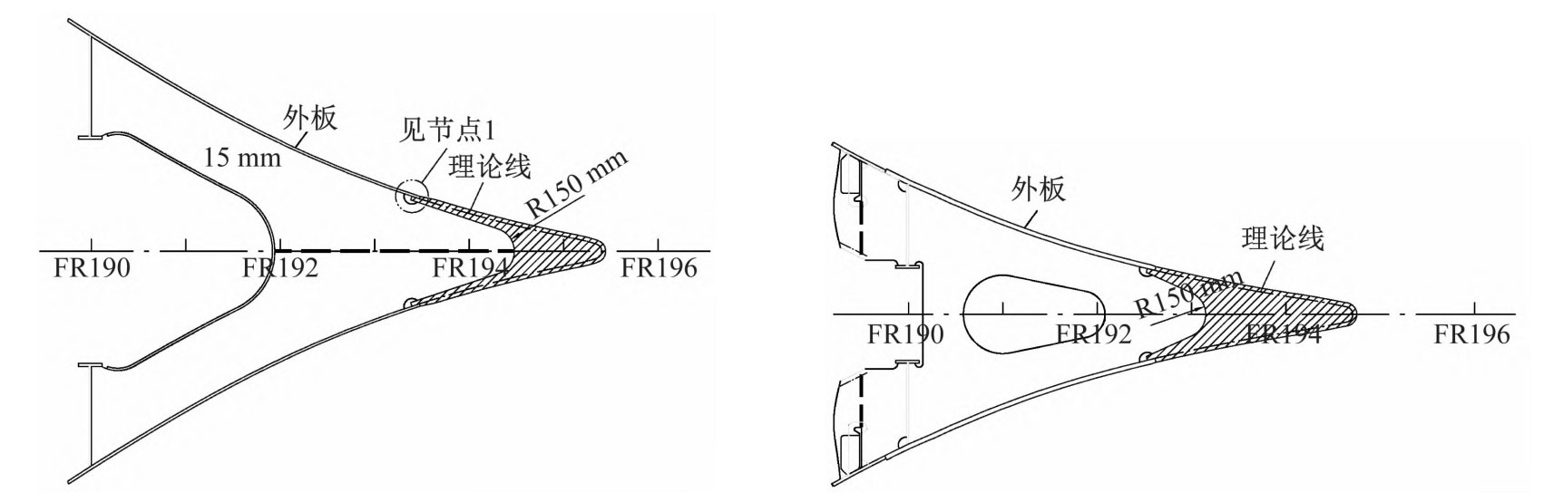
From Figure 1 and Figure 2, it can be seen that based on the detailed CAD section, some node drawings, and the symmetrical feature of the bow column steel casting, the port side (or starboard side) can be created, and the other side can be treated as a solid mirror. According to Figure 2, the linear information of some typical positions can be obtained, such as the contour line of the middle longitudinal section, the contour line of some horizontal plane intersections, and the structural form at the intersection with the outer plate. Generate spatial curves of partial profile contours by sketching in the middle longitudinal section and some horizontal planes.
2. Obtaining Line Patterns for Structural Interconnection
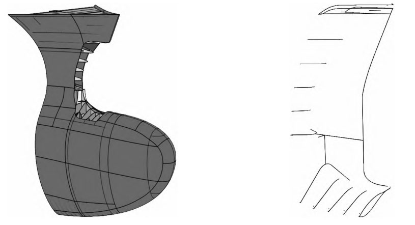
Figure 3 shows the hull structure of the bow column and its contour line at the connection with the steel casting. The bow column is located in the upper area of the bulbous bow of the hull. From Figure 3, it can be seen that for the structure connected to the bow column steel casting in this area, Extract (extraction function) is used to obtain the line shape of the intersection between the hull structure and the bow column steel casting. These curves are used as the skeleton lines of the internal surface of the bow column steel casting, and fitted into the internal surface of the bow column steel casting using Multi Sections Surface.
3. Surface Generation and Correction
After obtaining the typical profile information of the steel casting and the line information of the docking part with the hull structure, a bow column steel casting hull internal surface can be roughly constructed through the Multi Sections Surface and Fill function. This surface may have uneven or unreasonable conditions, and further improvement in its smoothness and accuracy is needed. By using the Intersection function, the key curves (or points) of the non smooth parts can be intercepted, the offset values of the curves (or points) can be adjusted, and the key points and line elements of the surface can be modified, discarded, and added to improve the smoothness of the fitted surface. After extracting key lines (or points), it is necessary to isolate the lines (or points) into isolated geometric elements by disconnecting them. Otherwise, re referencing may cause repeated referencing errors and fall into a dead cycle.
4. Generation of closed surfaces
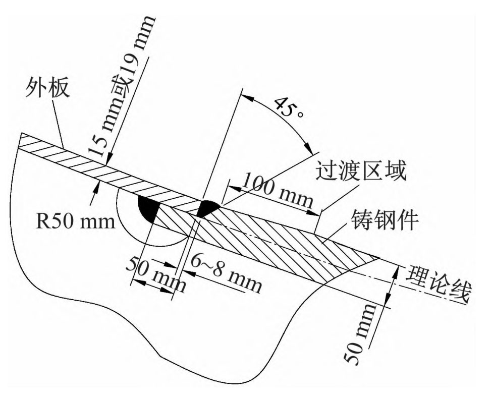
Extract the contour lines of the inner and outer plate surfaces of the bow column steel casting area (i.e. part of the outer plate boundary lines in Figure 2), and use the Split function in GWS to extract the outer plate surface of the bow column steel casting area from the outer plate. Extract the boundary of the modified surface, and according to the connection form between the node steel casting and the outer plate shown in Figure 4, make a node sketch on the plane, and publish it in segments in the form of features. Select multiple profiles on the boundary line and repeat similar operations. The published feature is swept along the surface boundary line to generate a new surface. Repeat the above operation using the boundary lines of the new surface, straight
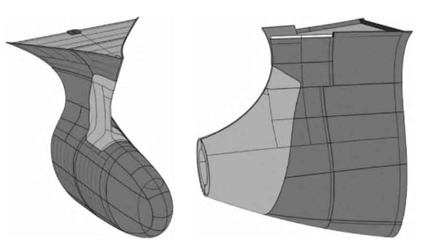
Connect the inner surface of the bow column cast steel hull with the outer plate surface in the form of nodes as shown in Figure 4, forming a closed surface.
5. Generation of physical models
Through the Join function in GWS, the modified surface, the repeated swept surface using the modified surface boundary line, and the outer plate surface can be joined together to form a spatial closed surface. In GWS, a solid model can be generated using spatial closed surfaces through the CloseSurface function. The solid model generated above is only the internal part of the hull outer plate. For the part that is aligned with the hull outer plate, the outer plate surface of the bow column steel casting area intercepted in Section 2.3 is generated as a solid using ThickSurface (thickened, with the same thickness as the outer plate in that area), and the solid part is joined with the previously generated surface envelope solid to obtain the final bow column steel casting solid model.