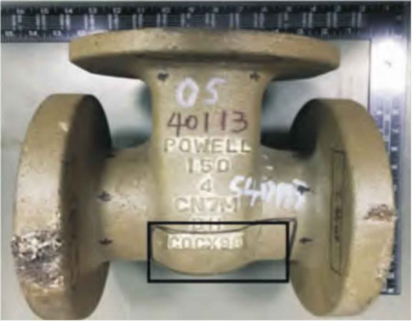
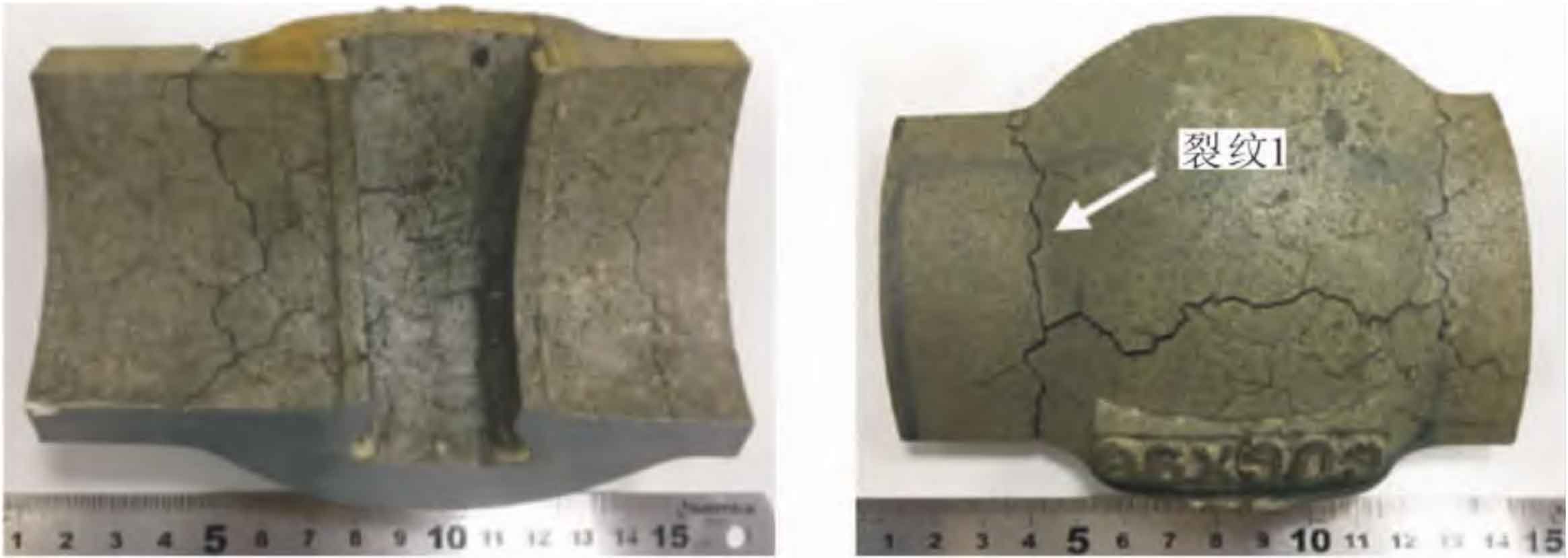
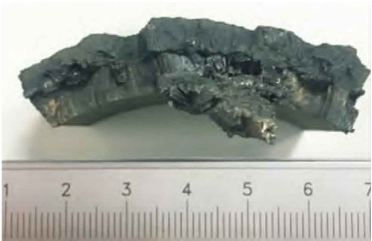
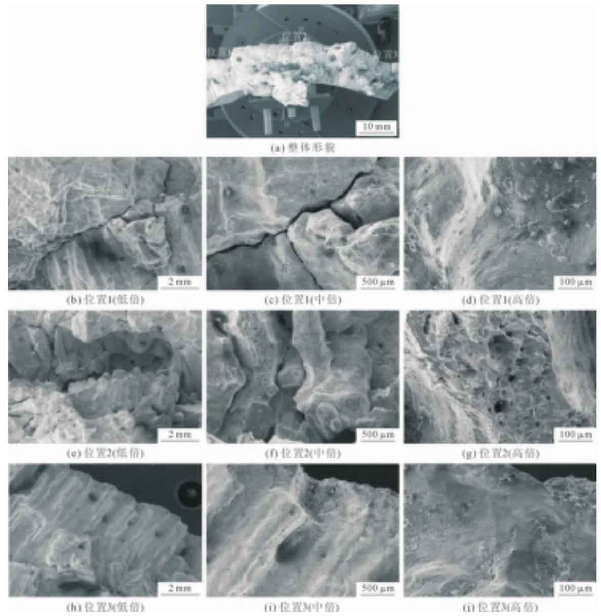
Cut a crack sample in the middle (see the black box position in Figure 1). The appearance of the crack on the inner and outer walls of the product is shown in Figure 2. The crack has penetrated the entire wall thickness. After cutting the crack along crack 1, the macroscopic morphology of the crack fracture is shown in Figure 3. As shown in Figure 3, the fracture surface of the crack is gray-black, with high-temperature oxidation morphology. The fracture surface cracks along the coarse columnar crystal, and the middle of the fracture surface is accompanied by porosity.
From the macroscopic fracture morphology of the crack, it can be judged that the crack is a hot crack in investment casting, and the fracture surface of the crack is seriously oxidized. It is preliminarily speculated that the temperature range of the crack is from 1200 ℃ to Ae3 (about 900 ℃), that is, it is formed in the second brittle zone.
After cleaning the sample, observe it under the scanning electron microscope. The microscopic morphology of crack 1 in Fig. 2 (b) is shown in Fig. 4. It can be seen that the fracture morphology of the three positions is similar, and the fracture surface is covered with a layer of high-temperature oxidation corrosion products. The fracture surface is obviously cracked along the columnar crystal, and obvious loose defects can be seen at the position of 1/2 wall thickness. In order to achieve the purpose of sequential solidification from the bottom to the top, during production, this investment casting was provided with a large riser, but there was porosity at the center of the thin wall, indicating that there were a large number of low melting point phases due to segregation during solidification, and finally solidified, forming a reverse feeding for the nearby parts.
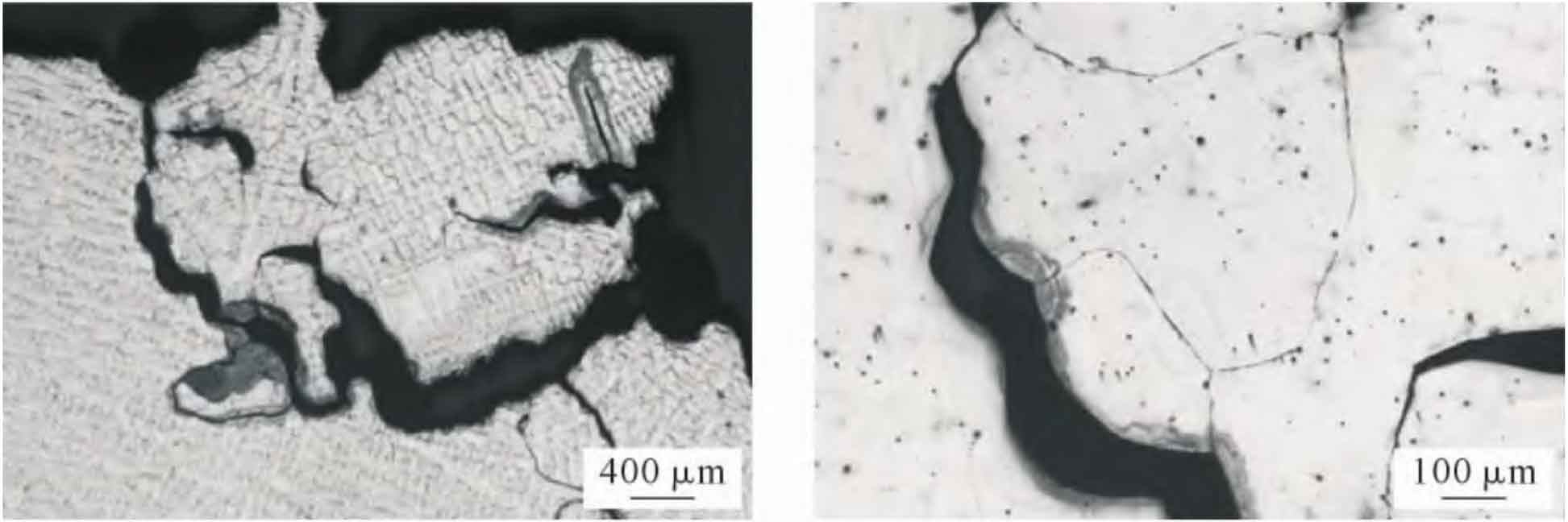
Cut the metallographic sample from the cracked product for metallographic inspection, and observe the metallographic structure near the crack. As shown in Figure 5, the cracks basically crack along the columnar grain, that is, along the original austenite grain boundary, and there are many loose defects. There are also a large number of intragranular precipitates in the matrix structure around the crack.
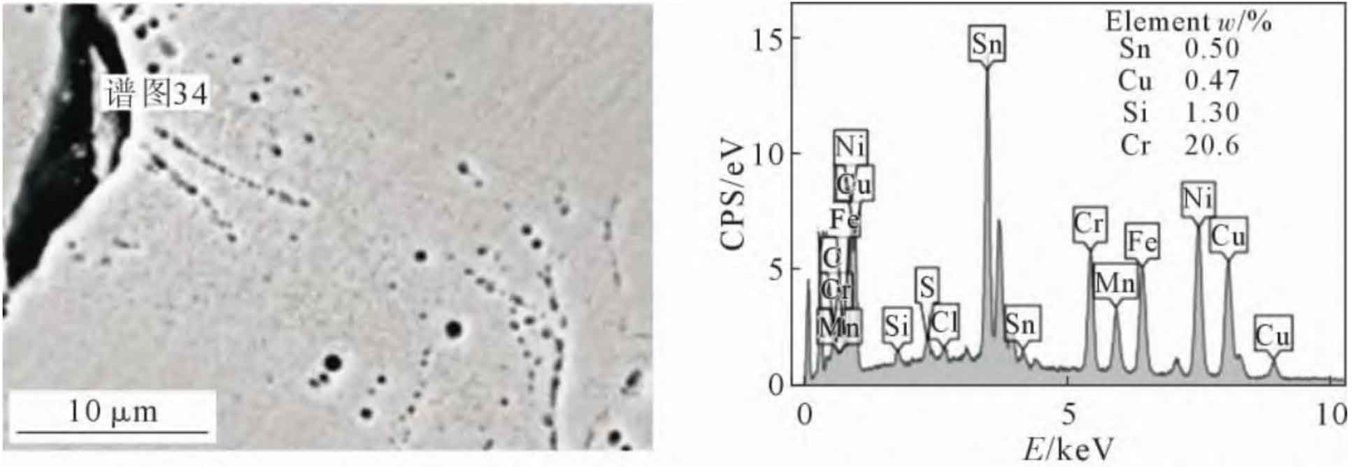
The metallographic sample was observed under the scanning electron microscope, and obvious intergranular inclusion particles were found at the crack. The energy spectrum scanning at this point is shown in Figure 6. It is found that the particle contains high concentration of low melting point element Sn, so it is speculated that the particle at the grain boundary may be a Cu-Sn binary alloy phase with low melting point. The presence of obvious inclusion particles or intergranular low melting point precipitated phase at the crack may lead to the appearance of hot cracks, which is also consistent with the characteristics of cracks formed in the second brittle zone. Therefore, it is necessary to retest the chemical composition of the original furnace charge to determine whether the Sn content in the chemical composition of the cracked product is too high.