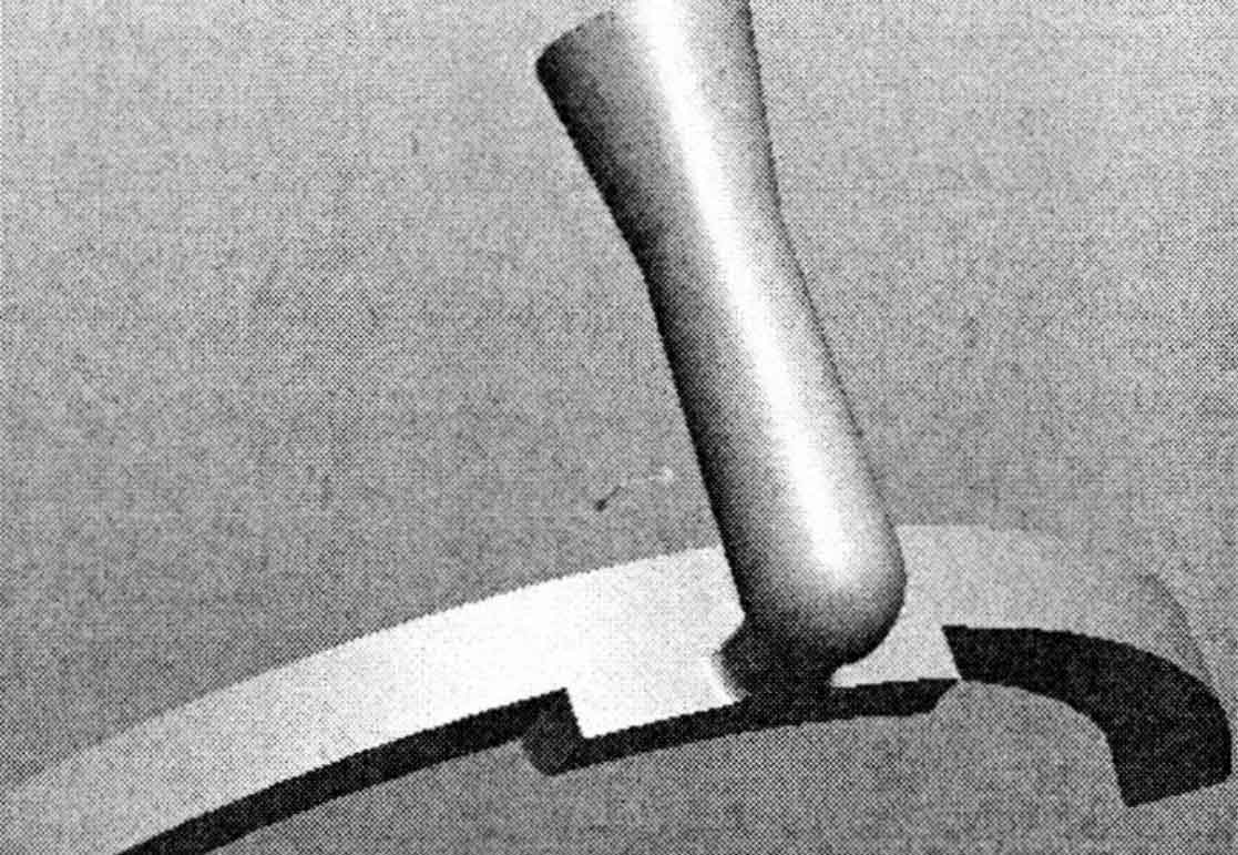
The experimental object is Flywheel Casting. The outer circle diameter of the casting is 350mm, the thickness is 39mm, and the material is QT600-3 (equivalent to the German standard gjs600). In order to realize stable and rapid mold filling, a semi closed gating system with a inner < a straight < a horizontal is adopted. The runner is annular and its cross section is trapezoidal. The right angle of the connecting part between the sprue and the runner is excessive to reduce the flow rate of molten metal, as shown in Figure 1. The overlapping part with the transverse runner increases the contact area to place the filter screen.
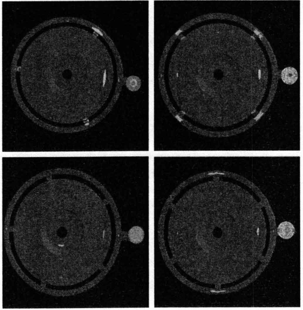
According to the theory of equilibrium solidification, the inner gate should be distributed with multiple gates. In this way, the molten iron can not only fill the cavity quickly and smoothly, but also disperse and balance the temperature field. The simulation results show that by simply increasing the number of gates, the shrinkage porosity tends to decrease and disperse, but it can not effectively reduce the occurrence of shrinkage porosity, as shown in Figure 2. In actual production, the whole ring-shaped runner is often not used, and only the inner runner is set on one side of the flywheel and distributed dispersedly. Therefore, the runner is semi-circular.
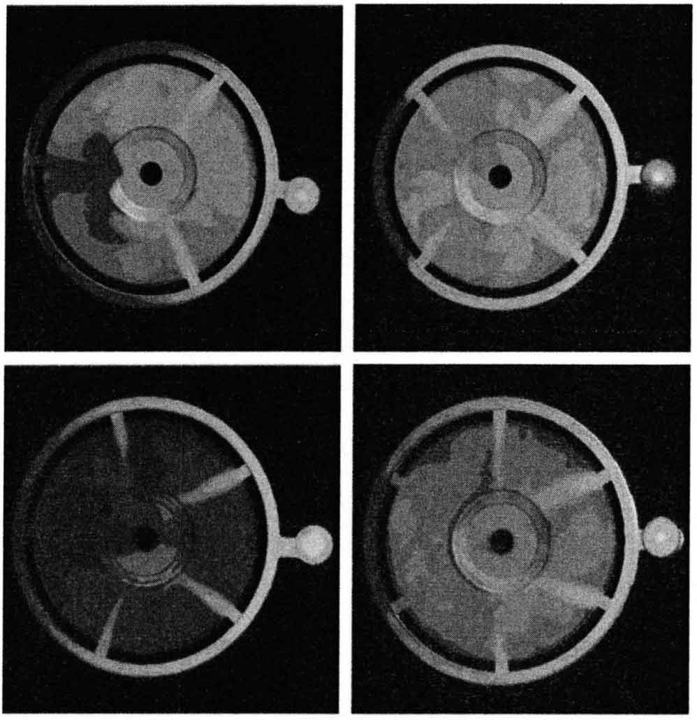
The complete annular transverse sprue and uniform symmetrical inner sprue can not obtain uniform temperature field distribution. Figure 3 shows the simulation results of temperature field distribution in the mold cavity when the flywheel casting is poured. The flywheel casting is close to the sprue – N temperature is high, and the other – N temperature is slightly low. In addition, the hot metal temperature of the inner gate near the sprue is high, and it still has a certain feeding effect after the mold filling is completed, while the inner gate far away from the sprue has solidified. The part adjacent to the sprue is not only the final solidification point, but also can not get the feeding of the inner sprue, so there will always be shrinkage defects.
| Scheme code | Sectional area of sprue | Cross sectional area of runner | Sectional area of internal sprue | Choke cross-sectional area | Σ straight: ∑ transverse: ∑ resistance |
| A | 706 | 814 | 360 | 360 | 1.96:2.26:1 |
| B | 706 | 814 | 560 | 450 | 1.57:1.81:1 |
| C | 706 | 814 | 360 | 360 | 1.96:2.26:1 |
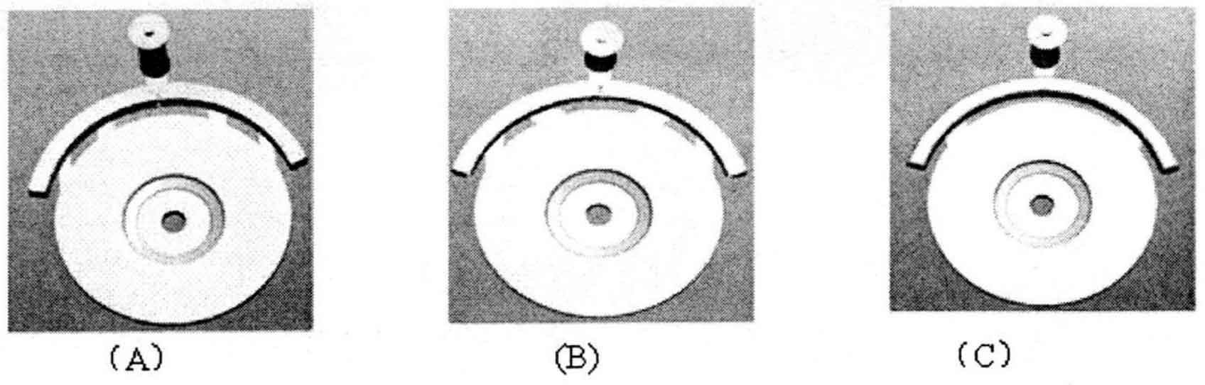
Before the experimental scheme is determined, after many explorations, the pouring process of Flywheel Casting is simulated in MAGMAsoft, and the improved effect is compared. Finally, three schemes are selected for actual pouring experiment verification. The three schemes are recorded as a, B and C respectively. The design parameters of Flywheel Casting gating system are shown in table. The upper runner diameter of three kinds of Flywheel Casting is 30mm. The transverse runner is also consistent, with a total cross-sectional area of 814mm2. The layout of the internal sprue is as follows: in scheme a, the four internal sprues extend straight to the cavity, the width of the two internal gates on the inner side is 25mm, the width of the two internal gates on the outer side is 20mm and the thickness is 4mm; The width of the two inner gates on the inner side of B is 45mm, 60 with xoz surface, as shown in Figure 4 (b); Included angle; The outer two inner gates are 25mm wide and 4mm thick; C middle inner sprue: 45mm wide and 4mm thick.