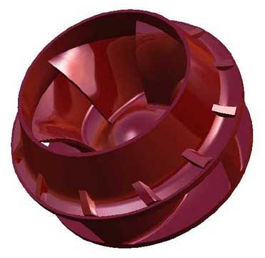
The surface of the blade of the sulfur pump impeller and the surface of the blade are calculated to achieve the ideal result of hydrodynamic distortion. The foam cutting can not be used. The foaming molding is used in this paper. The precondition of die making is the three-dimensional design of blade and die.
General free-form feature modeling steps include the following steps:
(1) Use spline function to build spline.
(2) The “primary” slice is constructed, which is realized by the functions of over curve, ruled line, over curve mesh and sweeping.
(3) Build a transition slice, using the facet; secondary section; soft rounding; face rounding; n-edge surface options.
(4) Analyze / edit free form data to ensure that the resulting surfaces are smooth and meet the requirements.
(5) The functions of thickening, stitching and trimming are used to build the solid.
Blade design sample drawing the point coordinates of the eight sections of the impeller on the working face and the back. Among them, there are 74 coordinate points on the working face and 74 coordinate points on the back, a total of 148 coordinate points. The designed curve is required to be smooth, continuous and wrinkle free. In order to meet such requirements, the general principles to be followed in modeling are proposed as follows:
(1) If the accuracy is guaranteed, try to use a lower degree of curve, and use the same degree for each curve. Because the constructed curve needs curvature continuity, the degree of this modeling curve is 5.
(2) Make sure that the surface you make passes through each data point.
(3) The boundary curve of the surface should be smooth and continuous to avoid sharp corners, intersections and overlaps.
(4) Ensure that the curvature of each curve changes evenly.
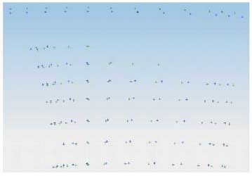
According to the above steps and design principles, firstly, 142 key data points are drawn on eight planes by using sketch function, as shown in the figure:
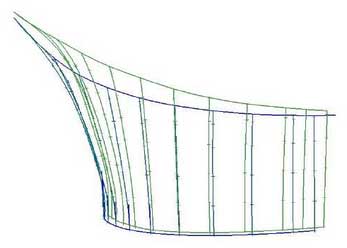
With the key data points, the next step is to use spline, bridge curve, project curve and other functions to draw the key curves of the working face and back. When drawing a curve, you should select through points to ensure that the curve passes through all data points. And ensure smooth curve. The curve drawn is as shown in the figure.
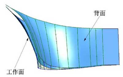
When the key curve is drawn, the next step is to make two surfaces of blade working surface and back surface. Making surface uses the through curve mesh, through curves function, trim, sew and other operations in the mesh surface function. In the process of drawing surface, it is required to ensure that the surface passes through all curves and the surface is smooth. The surface drawn is as shown in the figure:
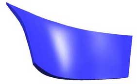
The operation of generating solid from surface is relatively simple, which can be completed by using trim, sew and other operations. As shown in the figure.
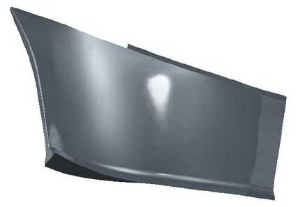
However, there are some differences between the final blade part drawing and the obtained blade 3D drawing. It is also necessary to consider the positioning with the core box and the matching with the hub, and the blades that have been drawn need to be processed once. The functions of extrude, offset, and combine bodies can be used. As shown in the figure, the designed blade parts drawing. The blade is simply arrayed and added to the impeller hub. The 3D model of the whole impeller can also be made. As shown in the figure.
