
The existing mould and the cast cylinder head with grinding problems are shown in Figure 1. As shown in Figure 1a, the grinding jig is composed of 4 support columns and 2 front and rear limit columns. During the grinding process, the limit column is inserted into the valve seat hole of the cast cylinder head for positioning. Limited by the production of different specifications of cast cylinder heads in the workshop, a single mold cannot be generalized. When grinding different cast cylinder heads, the grinding mold must be replaced as a whole, which will affect the production efficiency. At the same time, due to long-term continuous production, the positioning column is worn to varying degrees, which leads to the positioning deviation of the cast cylinder head, and the grinding of the cast cylinder head is uneven, which requires manual secondary grinding, and even directly leads to the scrapping of the cast cylinder head. Aiming at the problems of inaccurate positioning and poor universality of the grinding jig, the grinding jig design was optimized.

A kind of grinding mould suitable for the cleaning and grinding machine of the cast cylinder head is designed, which can realize the batch grinding of the batch gap of the cast cylinder head. The structure of the grinding mould is simple and reliable, and the universal grinding mould for different products can be realized by replacing components.
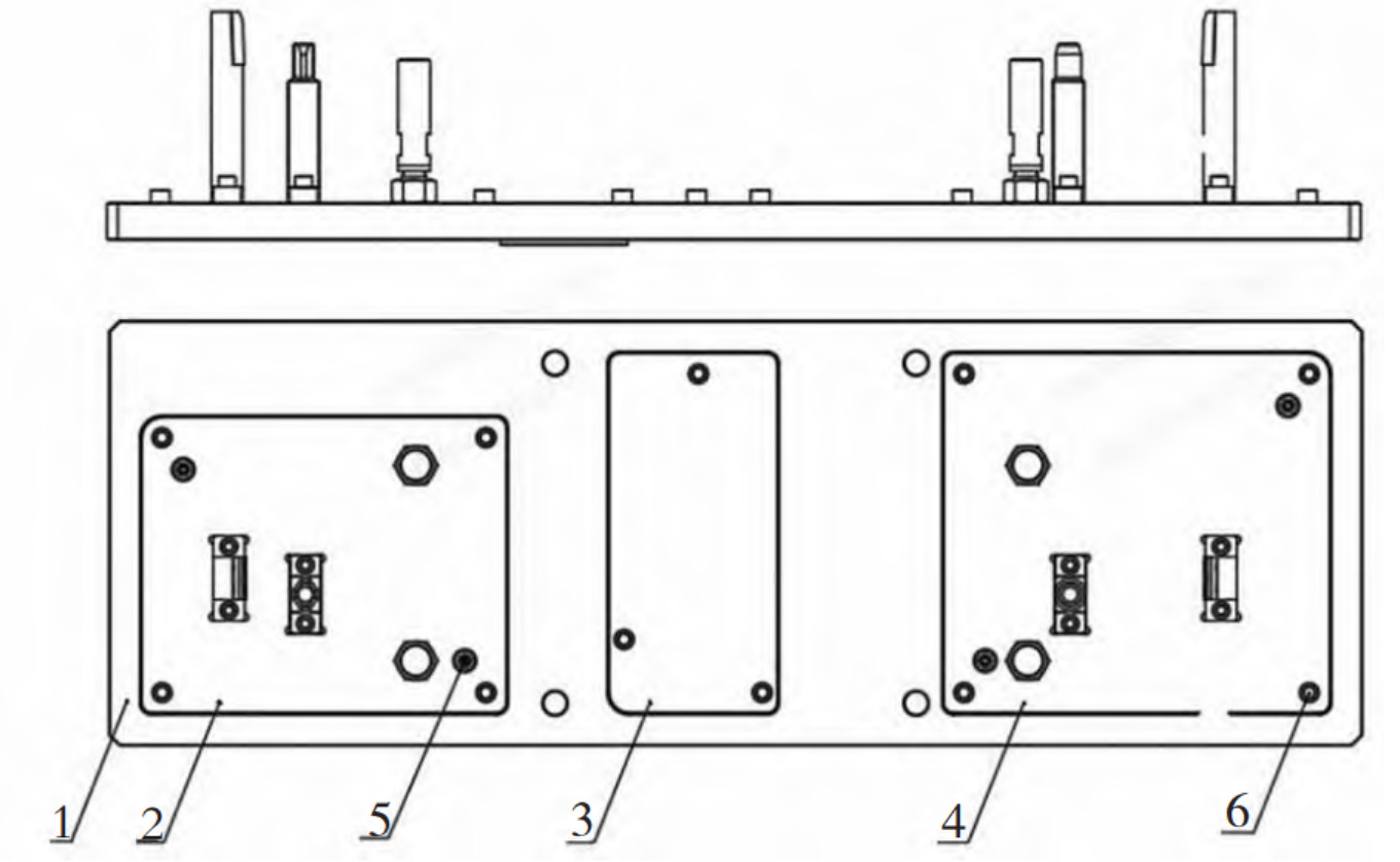
The overall structure of the grinding mould is shown in Figure 2, which is composed of base plate assembly, support assembly and limit assembly. The base plate assembly consists of base plate, insert a, insert B and insert C. To ensure the strength of the bottom plate assembly, the thickness of the bottom plate shall be controlled between 35mm and 50mm. The bottom plate shall be made into a sink structure. Insert a, insert B and insert C shall be placed at the sink position. The thickness of the insert shall be 20 mm ~ 25mm. The insert shall be positioned by two round locating pins at the opposite corners, and shall be tightly fixed by the fixing screws.
The structural design scheme of support assembly and limit assembly is shown in Figure 3. The support assembly and the limit assembly are fixed on the corresponding inserts through the sink structure and the fixing screws. The limit assembly is composed of a limit seat and a positioning column. The head of the positioning column is designed according to the shape of the grinding and casting cylinder head seat hole, and the head is subject to quenching and tempering treatment to increase the strength. The limit seat is equipped with a wear-resistant block, and there are gaskets of different thickness between the limit seat and the wear-resistant block. During the grinding process, the clearance between the limit column and the cast cylinder head is adjusted by adjusting the gasket, so as to realize the limit function of the cast cylinder head. The support column is equipped with a fixing nut to tighten the positioning column.
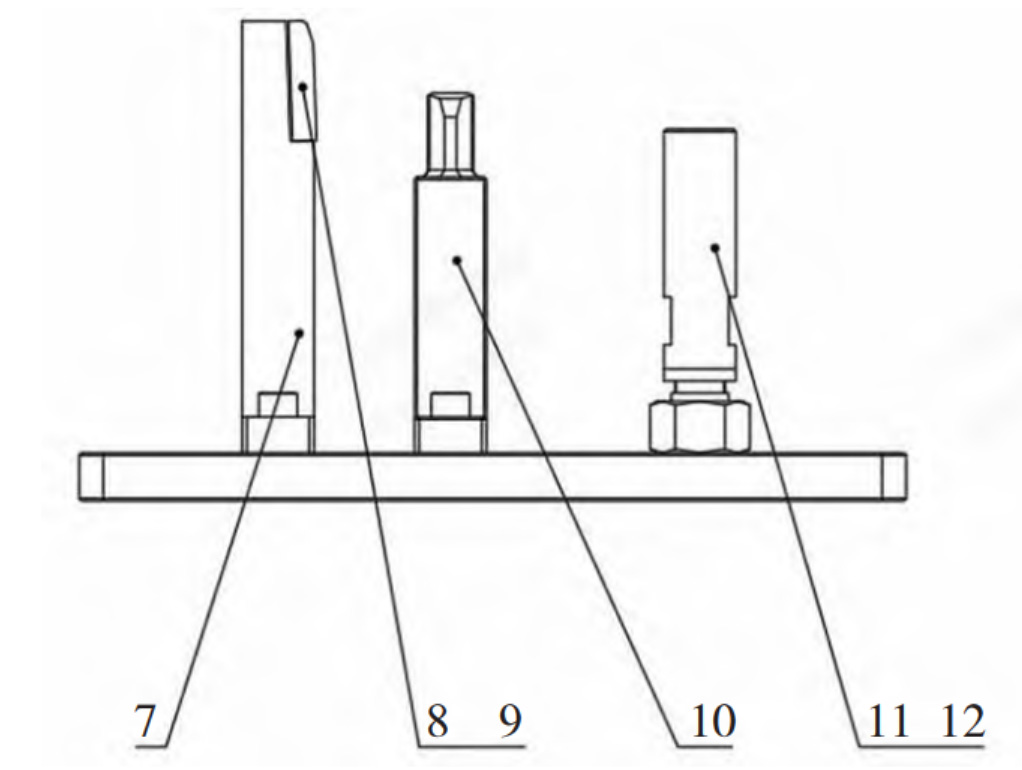
A limit seat is added to the support assembly to assist in limiting the front and rear ends of the cast cylinder head through the limit seat. It is inevitable that the grinding mould will be worn during use. When the positioning column is worn and causes positioning deviation, the gap between the limit seat and the cast cylinder head can be adjusted by adjusting the gasket on the limit seat, so as to achieve accurate positioning and avoid grinding deviation, resulting in uneven wall thickness of the casting and scrapping.
When different cast cylinder heads are switched, the grinding mould is realized by directly replacing the inserts corresponding to different cylinder heads. The positioning column structure on the insert corresponding to each cast cylinder head can be designed according to the product shape, which increases the universality of the grinding mould. It should be noted that in order to ensure the accurate and reliable positioning of the insert and the base plate, a 0.1mm gap is reserved between the insert and the base plate for clearance matching. At the same time, a positioning pin sleeve structure is configured. The gap + pin sleeve is used for positioning, and the fastening bolts are used for fixing after positioning.