In the automotive industry, the demand for high-performance engine components, particularly exhaust manifolds, has escalated with stringent emission regulations such as China’s Phase VI standards. These components must withstand extreme temperatures, often reaching 800–820°C, while maintaining structural integrity and thermal fatigue resistance. Traditionally, high-nickel austenitic spheroidal graphite iron has been employed for such applications due to its superior high-temperature properties, with a service temperature limit of approximately 880°C. However, this material incurs substantial manufacturing costs, primarily due to its high nickel content, which constitutes over 30% of the alloy composition. On the other hand, conventional silicon-molybdenum spheroidal graphite iron, while cost-effective, exhibits a limited service temperature of ≤760°C, rendering it inadequate for advanced engine designs. This dichotomy presented a significant challenge: developing a material that bridges the performance gap without the economic burden. Our research focused on optimizing the composition of silicon-molybdenum spheroidal graphite iron through the strategic addition of trace alloying elements, ultimately yielding a novel medium silicon molybdenum niobium spheroidal graphite iron. This material not only meets the rigorous thermal and mechanical requirements of modern exhaust systems but also drastically reduces production costs, fostering broader adoption in medium and high-end engines.
The core objective was to engineer a spheroidal graphite iron variant capable of enduring continuous operation at 820°C without deformation or cracking. Specifically, the target mechanical properties were set as follows: at room temperature, tensile strength (Rm) ≥ 600 MPa and yield strength (Rp) ≥ 500 MPa; at 780°C, Rm ≥ 70 MPa and Rp ≥ 50 MPa. Additionally, the material must survive rigorous bench tests, including 400-hour high-temperature endurance trials and 2000-hour variable load cycles. To achieve this, we embarked on a systematic material development program, exploring compositional adjustments and processing parameters. The initial phase involved comparative analysis of existing materials: standard silicon-molybdenum spheroidal graphite iron (Material 1), a modified version with minor nickel additions (Material 2), and high-nickel austenitic spheroidal graphite iron (Material 3). The chemical compositions and resultant mechanical properties of these materials are summarized in the tables below, providing a baseline for further optimization.
| Material | C | Si | Mn | P | S | Mo | Ni | Cr |
|---|---|---|---|---|---|---|---|---|
| Material 1 (Si-Mo SGI) | 3.25 | 4.28 | 0.0121 | 0.0337 | 0.00486 | 0.823 | — | 0.0532 |
| Material 2 (Si-Mo-Ni SGI) | 3.38 | 4.01 | 0.135 | 0.0294 | 0.0475 | 0.816 | 0.559 | 0.0392 |
| Material 3 (High-Ni Austenitic SGI) | 2.03 | 5.06 | 0.54 | 0.0223 | 0.0142 | 0.355 | 34.49 | 1.74 |
| Material | Rm (MPa) | Rp (MPa) | Elongation A (%) |
|---|---|---|---|
| Material 1 | 599, 601 | 509, 501 | 7.5, 7.5 |
| Material 2 | 615, 610 | 500, 505 | 9.5, 9.5 |
| Material 3 | 420, 418 | 240, 240 | 22, 22 |
| Material | Temperature | Rm (MPa) | Rp (MPa) | Elongation A (%) |
|---|---|---|---|---|
| Material 1 | 780°C | 55, 55, 54 | 33, 33, 33 | 41.5, 42, 46.5 |
| 820°C | 45, 46, 44 | 27, 28, 26 | 50, 48.5, 49 | |
| Material 2 | 780°C | 57, 56, 57 | 36, 33, 35 | 47, 46, 42 |
| 820°C | 44, 46, 46 | 26, 28, 27 | 48.5, 49, 40.5 | |
| Material 3 | 780°C | 149, 146, 136 | 82, 82, 75 | 23.5, 25, 28.5 |
| 880°C | 84, 79, 76 | 48, 45, 53 | 25.5, 24.5, 25 |
From these data, we observed that Material 2 exhibited slightly improved high-temperature strength over Material 1, but both fell short of the 70 MPa tensile strength target at 780°C. Material 3, while exceeding thermal performance requirements, suffered from low room temperature strength and prohibitive cost. This prompted us to delve deeper into alloy design. We hypothesized that synergistic effects from multiple trace elements could enhance the high-temperature capabilities of silicon-molybdenum spheroidal graphite iron. After extensive literature review and preliminary trials, we identified nickel (Ni), vanadium (V), and niobium (Nb) as promising additives. Nickel stabilizes the austenitic matrix at elevated temperatures, vanadium forms fine carbides that impede dislocation movement, and niobium contributes to precipitation strengthening and grain refinement. The interplay of these elements can be modeled using a generalized strength equation for spheroidal graphite iron at high temperatures:
$$ \sigma_{y}(T) = \sigma_0 + \Delta\sigma_{ss} + \Delta\sigma_{ppt} + \Delta\sigma_{gb} $$
where $\sigma_{y}(T)$ is the yield strength at temperature T, $\sigma_0$ is the lattice friction stress, $\Delta\sigma_{ss}$ is solid solution strengthening contribution, $\Delta\sigma_{ppt}$ is precipitation strengthening, and $\Delta\sigma_{gb}$ is grain boundary strengthening. For our alloy system, the contributions from Mo, Ni, V, and Nb are critical. For instance, the solid solution strengthening component can be approximated as:
$$ \Delta\sigma_{ss} = \sum k_i \cdot C_i^{2/3} $$
where $k_i$ is a strengthening coefficient for element i, and $C_i$ is its concentration. Molybdenum and silicon are known to provide substantial solid solution strengthening in ferritic matrices, but their effectiveness diminishes at high temperatures due to diffusion-controlled processes. Hence, we aimed to optimize their levels while introducing Nb and V to bolster precipitation hardening. After numerous iterative melts, we established an optimized composition range for the new medium silicon molybdenum niobium spheroidal graphite iron, as detailed in Table 4.
| Element | Target Range | Role in Alloy |
|---|---|---|
| C | 2.7–3.2 | Graphite formation, fluidity |
| Si | 4.1–4.3 | Ferrite stabilizer, improves oxidation resistance |
| Mn | 0.1–0.2 | Minimized to prevent pearlite formation |
| P | ≤0.04 | Impurity control |
| S | ≤0.01 | Impurity control, affects graphite morphology |
| Mo | 0.8–0.9 | Solid solution strengthener, enhances creep resistance |
| Ni | 0.7–0.9 | Austenite stabilizer, improves toughness |
| Nb | 0.6–0.7 | Forms NbC precipitates, refines grain structure |
| V | 0.19–0.23 | Forms VC precipitates, enhances high-temperature strength |
The melting and casting procedures were meticulously refined to ensure consistency. We employed a 300 kg medium-frequency induction furnace, using high-purity pig iron (C04 grade) as the base charge. Silicon carbide (SiC) with a granularity of 1–3 mm was added in two stages to promote inoculation and carbon adjustment. The charging sequence was critical: pig iron first, followed by half of the SiC, then scrap steel, returns, and molybdenum ferromanganese. Carburizer was added in two batches and submerged using scrap steel. After two-thirds of melting, the remaining SiC was introduced. Upon complete melting, nickel plate, ferrosilicon, niobium ferroalloy, and vanadium ferroalloy were added. The molten metal was superheated to 1450–1460°C for rapid sampling and spectral analysis. The entire process from melting to pouring was confined within 1.5 hours to prevent excessive oxidation and composition drift. Pouring temperatures were tightly controlled between 1390°C and 1440°C to ensure proper mold filling and minimize shrinkage defects.
To address the challenge of discrepancy between standard test coupons and actual castings—a common issue in complex thin-walled components like exhaust manifolds—we developed an innovative rapid sampling device. This device features a multi-section mold that replicates the varying wall thicknesses of the manifold: a thick section representing flanges, a transition zone, and a thin section representing the pipe walls. By analyzing samples from these different regions, we could real-time monitor the composition and microstructure, enabling immediate corrective actions during melting. This approach guaranteed that the material properties measured from coupons accurately reflected those of the final casting, significantly enhancing quality control. The effectiveness of this method is evident in the consistent mechanical properties achieved, as shown in Table 5.
| Condition | Tensile Strength Rm (MPa) | Yield Strength Rp (MPa) | Elongation A (%) | Hardness (HBW) |
|---|---|---|---|---|
| Room Temperature (20°C) | 630–746 | 530–580 | 1–4 | 220–295 |
| High Temperature (780°C) | 70–79 | 51–57 | 24–36 | — |
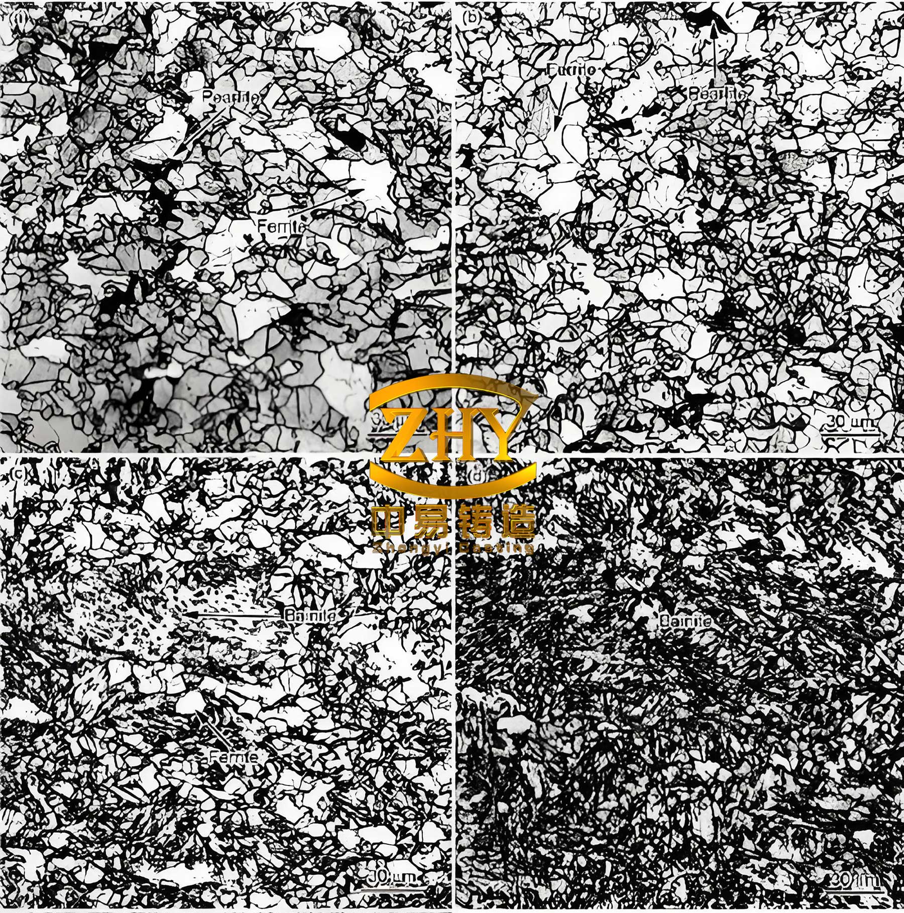
The microstructural evolution plays a pivotal role in determining the performance of spheroidal graphite iron. In our medium silicon molybdenum niobium variant, the graphite nodules are uniformly distributed and predominantly spherical, with a nodule count exceeding 150 nodules/mm². The matrix consists of a ferritic base with finely dispersed alloy carbides of Mo, Nb, and V. At elevated temperatures, these carbides resist coarsening, thereby maintaining strength. The addition of niobium is particularly beneficial; NbC precipitates with a lattice parameter similar to that of iron, providing coherent interfaces that hinder dislocation glide. The strengthening mechanism can be quantified using the Orowan bowing model for bypass of precipitates:
$$ \Delta\sigma_{ppt} = \frac{M \cdot G \cdot b}{2\pi \sqrt{1-\nu}} \cdot \frac{\ln(2\bar{r}/b)}{\lambda} $$
where M is the Taylor factor (~3.06 for ferrite), G is the shear modulus, b is the Burgers vector, ν is Poisson’s ratio, $\bar{r}$ is the average precipitate radius, and λ is the inter-precipitate spacing. By controlling the Nb and V content, we optimized λ to maximize strengthening without compromising ductility. Furthermore, silicon promotes the formation of a protective SiO₂ scale at high temperatures, enhancing oxidation resistance—a critical factor for exhaust manifolds exposed to cyclic thermal loads. The thermal fatigue resistance, a key performance metric, can be estimated using the Coffin-Manson relation adapted for cast irons:
$$ N_f = C \cdot (\Delta \epsilon_{th})^{-m} $$
where $N_f$ is the number of cycles to failure, $\Delta \epsilon_{th}$ is the thermal strain range, and C and m are material constants. Our material exhibits a high C value due to its enhanced high-temperature strength and ductility, resulting in superior thermal fatigue life compared to conventional silicon-molybdenum spheroidal graphite iron.
The casting of exhaust manifolds from this new spheroidal graphite iron presented unique challenges due to the component’s complex geometry with varying wall thicknesses and isolated hot spots. To mitigate shrinkage porosity and cavities in these regions, we implemented a combined approach of exothermic risers, chilling inserts, and vent pins. The exothermic risers provided supplemental heat to feed thick sections, while chills accelerated cooling in adjacent areas to promote directional solidification. Vent pins ensured proper escape of gases, reducing bubble entrapment. This composite technique proved highly effective across multiple product designs, ensuring sound castings with minimal defect rates. Below is a summary of the optimized process parameters for casting medium silicon molybdenum niobium spheroidal graphite iron exhaust manifolds.
| Parameter | Value or Range |
|---|---|
| Melting Furnace | 300 kg Medium-Frequency Induction |
| Charge Materials | C04 Pig Iron, SiC (1–3 mm), Scrap Steel, Returns, FeMo, FeNi, FeNb, FeV |
| Superheating Temperature | 1450–1460°C |
| Pouring Temperature | 1390–1440°C |
| Molding Method | Green Sand or Shell Molding |
| Riser Design | Exothermic Sleeves for Hot Spots |
| Chill Usage | Copper or Iron Chills in Critical Areas |
| Solidification Time Control | ≤ 5 minutes for thin sections |
The successful development of this advanced spheroidal graphite iron material enabled its deployment in numerous exhaust manifold applications for medium and high-end engines. We partnered with several automotive OEMs and tier-one suppliers, including FAW Jiefang and Faurecia, to validate performance under real-world conditions. Prototypes underwent exhaustive testing, such as 400-hour high-temperature endurance bench tests at 820°C, 250-hour thermal shock cycles (alternating between room temperature and 820°C), and 2000-hour variable load simulations. In all cases, the manifolds crafted from medium silicon molybdenum niobium spheroidal graphite iron exhibited no cracks, deformations, or failures. Moreover, the material’s oxidation resistance was exceptional, with scale formation less than 0.1 mm after prolonged exposure. The economic impact has been substantial: the manufacturing cost of these manifolds is less than one-third that of counterparts made from high-nickel austenitic spheroidal graphite iron, while performance meets or exceeds specifications. To date, over 40 distinct exhaust manifold designs have been successfully converted to this material, catering to more than 10 engine series, with annual production volume exceeding millions of units and generating significant revenue.
In conclusion, the innovation lies not only in the material composition but also in the integrated approach to process control and quality assurance. The medium silicon molybdenum niobium spheroidal graphite iron represents a breakthrough in cast iron technology, offering an optimal balance of high-temperature strength, thermal fatigue resistance, and cost-effectiveness. Its adoption aligns with industry trends toward sustainable and economical manufacturing without compromising performance. Future work may focus on further refining the alloy through computational thermodynamics to explore additional elemental synergies, as well as extending applications to other high-temperature components like turbocharger housings and exhaust diffusers. The journey underscores the importance of persistent experimentation and cross-disciplinary collaboration in advancing materials science for demanding engineering applications.