This article focuses on the casting process of nodular cast iron differential cases. It details the technical requirements, initial process design, sample trial production, improvement measures, and final production results. Through a series of research and optimization, a casting process that meets the quality requirements and production efficiency is achieved, providing a reference for the production of similar products.
1. Introduction
The differential case is an important component in the automotive transmission system. The quality of its casting directly affects the performance and reliability of the entire transmission. Nodular cast iron, with its excellent mechanical properties, is widely used in the production of differential cases. However, due to the complex structure of the differential case and high quality requirements, it is necessary to continuously explore and optimize the casting process to ensure product quality.
2. Technical Requirements
2.1 Design Specifications
The split 9AT differential case has a unique design. The finished single piece weighs 2.32 kg, and the blank single piece weighs 3.32 kg. It has 4 windows and 3 pin holes, and there are 3 asymmetric bosses on the flange surface. The diameter reaches 161 mm, and the flange thickness of the blank is 8.3 mm. These design features pose challenges to the casting process.
| Items | Specifications |
|---|---|
| Weight of finished piece | 2.32 kg |
| Weight of blank | 3.32 kg |
| Number of windows | 4 |
| Number of pin holes | 3 |
| Diameter | 161 mm |
| Flange thickness of blank | 8.3 mm |
2.2 Material and Quality Requirements
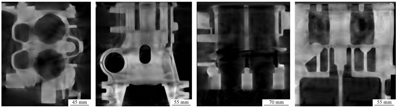
The material of the differential case is QT600 – M (enterprise standard). The chemical composition needs to meet specific requirements (see Table 1). In terms of quality, the misalignment requirement is ≤ 0.5 mm. In the development stage, the metallographic, hardness, and porosity need to be detected at specific positions including the shaft head and flange R angle. 100% X-ray inspection is required in the sample stage, and the CT inspection of the processed product by the customer requires that the internal defects meet the D3/1 standard, that is, the defect area accounts for less than 3% of the maximum square area of the cross-section, and the maximum diameter of a single defect is less than 1 mm. The appearance and internal defect requirements are shown in Table 2 and Table 3.
| Element | Content (mass fraction, %) |
|---|---|
| S | 0.02 |
| Si | 1.8 – 3.0 |
| Mn | 0.2 – 1.0 |
| P | ≤ 0.06 |
| Cu | 0.2 – 1.0 |
| Ti | ≤ 0.06 |
| Sn | 0.06 |
| Mg | 0.027 – 0.06 |
| Casting dimension tolerance/mm | Casting profile/mm | Defect requirements |
|---|---|---|
| ISO 8062 – CT9 | 2(±1) | Appearance defects: For key machined surfaces, defects with a diameter ≤ 1 mm and a depth ≤ 1 mm are allowed; for non-key machined surfaces, defects with a diameter ≤ 3 mm and a depth ≤ 1 mm are allowed; for blank surfaces, visible hole defects with a diameter ≤ 4 mm and a depth ≤ 1 mm are allowed. Internal defects: Porosity meets D3/1, and X-ray inspection meets ASTM E – 446 ≤ level 2. |
| Tensile strength/MPa | Yield strength/MPa | Elongation (%) | Hardness (HBW) | Nodularity (%) | Graphite type | Pearlite (%) | Carbide and phosphide eutectic (%) |
|---|---|---|---|---|---|---|---|
| 650 | 405 | 3 | 200 – 265 | 80 | V + VI | 55 | 3 |
3. Process Scheme
3.1 Riser Design
Considering the characteristics of the differential case such as thin flange design, multiple windows and pin holes, and high client requirements for internal porosity, a double-riser scheme is initially adopted. Two risers are set at the flange positions corresponding to two of the pin holes on the casting. According to the casting weight and structural dimensions, rectangular risers are designed to improve the process yield. The edges of the rectangular risers are rounded with a large radius R10 for weight reduction. At the same time, a common riser is reasonably arranged in the middle position. Finally, a design scheme of 2 castings corresponding to 3 risers is adopted. The size of the single riser on both sides is 120 mm × 43 mm × 50 mm. To achieve the best feeding effect, the riser neck is designed to be maximized. After removing the separation stop height of 0.5 mm, the riser neck height is designed to be 7.7 mm, and the riser neck length is designed to be 55 mm, so that the cross-sectional area of the riser neck reaches 423 mm². To reduce the weight of the single riser and meet the needs of liquid feeding, a 15 mm weight reduction pressure groove is designed at the top of the riser, and a separation block with a height of 15 mm is designed at the bottom. The final single weight of the riser on both sides is 2.1 kg, and the modulus is 6 mm. The common riser in the middle is designed with reference to the single riser. The size of the common riser is 120 mm × 55 mm × 50 mm, the bottom pressure groove is 15 mm, and the separation block height is 15 mm.
3.2 Gating System Design
The gating system adopts a lap joint design to improve the appearance quality of the differential case. The vertical runner and the horizontal runner are lapped once, the vertical runners are lapped again through a 6 mm thin sheet, and finally the ingate and the vertical runner are lapped three times. Through multiple lap joints and the use of thin and wide runners, the functions of flow resistance and slag blocking are achieved. The final ingate enters the iron from the bottom of the riser, which slows down the impact of the iron flow on the sand mold and prevents impurities from entering the casting cavity during the filling process.
3.3 Shaft Head and Other Position Treatments
To ensure that the shrinkage porosity at the shaft head position meets the D3/1 defect requirement, according to practical development experience, a shaft head position filling process is adopted for the shrinkage holes and shrinkage porosities of the isolated hot spots at the shaft head position of the differential case. Only 60% of the shaft head needs to be filled. That is, when the total height of the shaft head is 48 mm, filling 29 mm can achieve the goal. To reduce the consumption of sand cores, a part of the inner cavity of the shaft head is formed by the outer mold. The inner hole diameter is φ39 mm. To facilitate demolding, a 14 mm outer mold forming is designed at the corresponding position, and the demolding slope is designed to be 15°. The filled position is later machined together with the shrinkage holes and shrinkage porosities through machining. To address the concave shrinkage of the flange at the riser position, a 0.5 mm thickness subsidy is provided at the corresponding flange position, which is also beneficial to the casting feeding. At the same time, a cold needle with a size of φ6 mm × 25 mm and a demolding slope of 3° is set at the pin hole position.
4. Sample Trial Production and Improvement
4.1 Initial Trial Production Results
During the initial trial production using the above scheme, it was found that the pouring time was long and unstable, ranging from 13 to 16 s, which affected the production rhythm of the on-site molding. After testing the samples, the appearance and dimensions were all qualified, the full mold material and porosity detection were qualified, 100% X-ray inspection showed no internal defects, and the third-party CT inspection by the client was also qualified.
4.2 Process Optimization
4.2.1 Pouring Time Optimization
The analysis shows that the long and unstable pouring time is affected by the exhaust. Since the sand core volume of the differential case is relatively large, gas is generated during the pouring process when the sand core is burned, which affects the pouring time. In the new process scheme, exhaust sheets are added to the horizontal runner for exhaust, and the bottom of the exhaust sheets is made into a separation block for use.
4.2.2 Process Yield Improvement
To improve the process yield, two vertical runners are cancelled, and the horizontal runner is weight-reduced. The ingate directly enters the iron from the top of the riser, and the ingate entering the riser is lapped. The new improved process scheme shortens the pouring time and meets the on-site production rhythm. The process yield is increased from 36.7% to 42.7%. The main reason for the relatively low process yield is that the casting has a large diameter and thin thickness, and risers need to be added to meet the internal defect requirements.
5. Mass Production and Quality Control
After the process optimization, the differential case has entered mass production. In a certain month, 1,887 pieces were inspected for appearance, and 62 pieces were defective, with a pass rate of 96.71%. Among them, there were 37 pieces with sand holes on the appearance, with a defective rate of 1.96%; 18 pieces with bumps and bruises, with a defective rate of 0.95%; and 7 pieces with unclear casting marks after shot blasting, with a defective rate of 0.37%. The defective rate in the client’s processing is less than 1%, reaching the product development goal.
6. Conclusion
Through the research and optimization of the casting process of the nodular cast iron differential case, a process scheme that meets the quality requirements and production efficiency has been obtained. In the process, the riser design, gating system design, and treatment of key positions such as the shaft head are continuously optimized, and the problems in the trial production process are effectively solved. The successful mass production of the product provides a reference for the production of similar products in the industry. Future research can focus on further improving the process efficiency and reducing production costs while ensuring product quality.
In the actual writing process, relevant pictures can be added according to the content, such as pictures of the differential case structure, the casting process flow chart, and the comparison pictures before and after process improvement. These pictures can help readers better understand the text content and enhance the visual effect of the article. At the same time, in the text description, more detailed explanations and analyses can be added to make the content more in-depth and comprehensive.