
In my work on advanced nuclear fuel components, I encountered the challenge of producing a new type of fuel assembly bottom nozzle with complex geometry and stringent quality requirements. The component is made of austenitic stainless steel with a ferrite content between 10% and 30%, which demands excellent corrosion resistance and mechanical integrity. After extensive experimentation, I successfully developed a high precision investment casting process that meets all technical specifications. This article describes the key innovations and process controls that enabled the production of this critical component.
Component Geometry and Casting Challenges
The bottom nozzle has an overall dimension of 214 mm × 214 mm × 80 mm. It features a square frame plate with 264 specially shaped flow holes and four supporting legs. The flow holes are arranged in a dense grid, and the walls between them are extremely thin, ranging from 0.5 mm to 2.65 mm in thickness. The surface roughness requirement is Ra = 3.2 μm, which is at the limit of what conventional investment casting can achieve. Additionally, the component contains 264 curved protrusions on the top surface and 25 guide tube holes, all of which must be cast to near-net shape without subsequent machining. The casting material is CF3 grade austenitic‑ferritic stainless steel, with a controlled cobalt content below 0.04% to minimize neutron absorption. The chemical composition limits are summarized in Table 1.
| Element | C | Si | Mn | P | S | Cr | Ni | Mo | N | Co | Fe |
|---|---|---|---|---|---|---|---|---|---|---|---|
| Min | – | – | – | – | – | 17.0 | 9.0 | – | – | – | Bal. |
| Max | 0.03 | 1.2 | 2.3 | 0.03 | 0.04 | 20.0 | 12.0 | 0.5 | 0.08 | 0.04 | Bal. |
The ferrite content must be maintained between 10% and 30% according to ASTM A799‑2010. Achieving this duplex microstructure while avoiding casting defects such as mistun, shrinkage porosity, and surface pitting required a systematic optimization of the high precision investment casting route.
Several critical difficulties emerged during the initial trials:
- The large surface area and intricate internal passages made it challenging to obtain a smooth surface finish of Ra 3.2 μm.
- The 0.5 mm thin walls of the flow holes are prone to incomplete filling (mistun) because the molten metal must travel more than 210 mm from the gating system to the farthest edges.
- The simultaneous presence of thin ribs and thick sections (e.g., the 21.5 mm thick legs) creates differential shrinkage, leading to warpage of the wax pattern and the final casting.
- The 264 curved protrusions and 25 guide tube holes could not be fed by conventional risers, so local shrinkage might occur.
Optimization of the Gating System
The gating system design was the first major improvement. Initially, I used a multi‑layer runner system with a double‑level cross runner, hoping to distribute the metal evenly. However, this design caused severe mistun on the thin ribs and the small curved bosses. After analyzing the flow pattern, I removed the intermediate cross runner, allowing the molten metal to enter the mold cavity directly from the bottom and quickly fill the thin‑section flow holes. Figure 1a shows the original gating layout, and Figure 1b the optimized version. (Note: figures are not reproduced here, but the description is sufficient.)
The optimized system uses a single bottom runner that directs metal into the central area of the square frame, from where it flows radially outward to the thin ribs. This arrangement minimizes the flow distance to the thinnest sections and avoids direct impingement on the guide tube holes, which previously caused surface pitting. The final casting exhibited complete filling of all 264 flow holes and the 0.5 mm edge thickness, with no mistun or cold shut defects.
Wax Pattern and Mold Shell Development
For the wax pattern, I initially tried a polystyrene‑based filler (XLPS) but the pattern surface quality was inadequate. I then switched to a domestic UV‑curable resin, which improved hardness and surface finish, but the thermal expansion coefficient was too high. When the pattern was heated during dewaxing, it expanded excessively and cracked the ceramic shell. Finally, I selected an imported desktop‑grade photosensitive resin specifically designed for investment casting patterns. This resin has a low coefficient of thermal expansion and high dimensional stability. To reduce material cost and weight, I designed the pattern as a hollow structure with an internal grid‑rib support.
For the ceramic shell, I used a silica sol binder with pH 9.0–9.5 and zircon flour (320 mesh) as the refractory. The slurry composition is given in Table 2.
| Component | Amount |
|---|---|
| Silica sol (binder) | Diluted with deionized water |
| pH of diluted sol | 9.0–9.5 |
| Zircon flour (320 mesh) | Powder‑to‑liquid ratio 1:3 |
| Wetting agent | ~20 mL |
| Defoamer | ~16 mL |
The shell was built in nine coats. The face coat used 100/120 mesh zircon sand, the transition coat used 30/60 mesh zircon sand, and the backup coats used 16/30 mesh Shangdian sand. Each coat was applied by rain‑type sanding. Drying time for the face coat was 24 h, while transition and backup coats each required 48 h at controlled temperature and humidity.
For dewaxing, I employed a rapid method using a hot air gun to melt and remove the wax from the sprue center, leaving the main pattern body unaffected. This prevented thermal shock that could crack the shell. The shell was then fired in a gas‑fired furnace: first heated slowly to 550 °C, then rapidly to 900 °C and held for 2 h to ensure complete burnout of residual wax.
Melting and Pouring
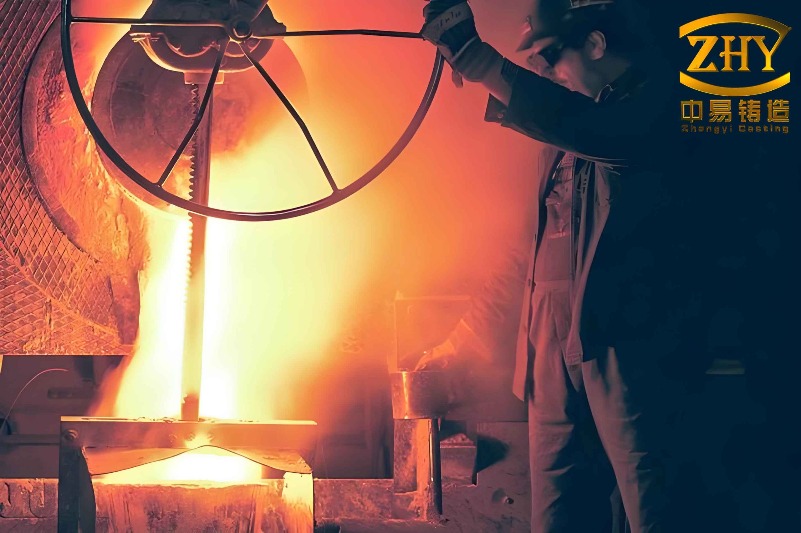
The raw material was dry‑blasted and preheated at 400 °C for 1.5 h before charging into a vacuum induction melting furnace. I melted 50 kg of steel per heat. Before pouring the actual casting, a test coupon was poured to verify chemistry and ferrite content. The shell was placed in a dedicated sand box and preheated to 1150 °C in a furnace. After holding at that temperature for at least 3 h, the sand box was taken out and pouring was completed within 25 min. The pouring temperature was controlled between 1500 °C and 1600 °C, with a vacuum level below 1.5 Pa. The pouring time was less than 3 s to minimize heat loss and oxidation.
Shell Removal and Cleaning
The ceramic shell was removed by alkaline boiling. The castings were immersed in a 30 wt% NaOH solution at a pressure of 0.2 MPa for 0.3 h. This caustic bath effectively dissolved the silica‑based binder and loosened the refractory particles, allowing easy cleaning of the complex internal passages and the 0.5 mm thin slots. No mechanical intervention was needed, preserving the delicate features.
Heat Treatment and Surface Finish
After initial rough machining, the castings were solution heat treated in a box‑type resistance furnace at 1050–1070 °C for 3 h, followed by water quenching. This achieved the desired duplex microstructure with 10–30% ferrite. Subsequently, the castings were shot‑peened to improve the surface condition. Shot peening created a ~10 μm thick layer of refined grains with twin boundaries extending approximately 50 μm inward. This deformed layer promoted rapid diffusion of chromium to the surface, facilitating the formation of a dense, protective Cr2O3 oxide scale during subsequent high‑temperature exposure.
To quantify the benefit of shot peening on oxidation resistance, I performed steam oxidation tests at 620 °C for 1000 h on both shot‑peened and unpeened specimens. The results are summarized in Table 3.
| Condition | Oxide morphology | Cr content in oxide (at%) | Oxide protectiveness |
|---|---|---|---|
| Without shot peening | Irregular nodules (~100 µm) and porous Fe‑rich oxide islands | 34.16% | Non‑uniform, susceptible to spallation |
| With shot peening | Uniform, fine‑grained, dense Cr‑rich oxide; no nodules | 51.74% | Excellent; enhanced corrosion resistance |
The shot‑peened surface exhibited a Cr content of 51.74 at%, significantly higher than the 34.16 at% on the unpeened sample. This Cr‑enriched oxide layer is more protective under the high‑temperature, high‑pressure water environment inside a nuclear reactor.
Dimensional and Quality Control
Throughout the development, I applied statistical process control to monitor key parameters. Table 4 lists the main process windows that were established for consistent production of high precision investment casting.
| Parameter | Target value / range |
|---|---|
| Wax pattern shrinkage | 0.8%–1.2% linear |
| Shell thickness (average) | 6–8 mm |
| Shell firing temperature | 900 °C ± 10 °C |
| Pouring temperature | 1550 °C ± 50 °C |
| Vacuum level during pouring | ≤1.5 Pa |
| Pouring time | ≤3 s |
| Solution treatment temperature | 1060 °C ± 10 °C |
| Ferrite content (final) | 10%–30% |
| Surface roughness Ra | ≤3.2 μm |
One of the most critical aspects was controlling the solidification shrinkage to avoid distortion. The combination of thin ribs (0.5 mm) and thick legs (21.5 mm) creates a large thermal gradient. To counteract warpage, I added temporary reinforcing ribs on the wax pattern at strategic locations. These ribs were later removed during final machining.
Mathematical Modeling of Filling Behavior
To better understand the filling of the thin‑walled sections, I used a simplified flow model. The flow velocity of molten metal through a narrow channel can be approximated by the Bernoulli equation with friction losses. For a vertical runner of height \( h \) and a horizontal thin‑section of length \( L \) and thickness \( t \), the pressure drop is:
$$
\Delta P = \rho g h – \frac{1}{2} \rho v^2 – f \frac{L}{D_h} \frac{\rho v^2}{2}
$$
where \( \rho \) is the density of molten steel (≈7000 kg/m³), \( g \) is gravitational acceleration, \( v \) is the average velocity, \( D_h \) is the hydraulic diameter of the thin section, and \( f \) is the Darcy friction factor. For laminar flow in a narrow slot, \( f = 96/Re \), and the Reynolds number \( Re = \rho v D_h / \mu \). The critical condition for complete filling is that the pressure at the end of the thin section remains above the vapor pressure of the metal. By iterating with the measured viscosity \( \mu \approx 6 \times 10^{-3} \, \text{Pa·s} \) at 1550 °C, I determined that the optimized gating system provides a velocity of ~1.5 m/s and a pressure head sufficient to fill a 210 mm long thin slot of 0.5 mm thickness.
The solidification time \( t_s \) for a thin wall can be estimated using Chvorinov’s rule:
$$
t_s = C \left( \frac{V}{A} \right)^2
$$
where \( V \) is the volume, \( A \) is the cooling surface area, and \( C \) is a mold constant. For the 0.5 mm thick rib, the modulus \( V/A ≈ 0.25 mm \), giving a solidification time of only a few seconds. This rapid solidification demands that the metal is poured quickly and that the shell is preheated to avoid premature chilling. The shell preheat of 1150 °C was therefore essential to maintain fluidity.
Results and Conclusions
Through systematic optimization of the gating system, wax pattern material, shell building parameters, melting and pouring conditions, and post‑casting treatments, I successfully produced bottom nozzles that fully comply with the technical requirements. The key achievements are:
- Complete filling of all 264 flow holes with minimum wall thickness of 0.5 mm.
- Surface roughness Ra ≤ 3.2 μm achieved without additional machining on most internal surfaces.
- Ferrite content consistently in the range of 10%–30%.
- Excellent oxidation resistance after shot peening, with a dense Cr‑rich oxide layer.
The high precision investment casting process developed here provides a reliable and cost‑effective route for manufacturing complex nuclear fuel components with demanding dimensional and metallurgical requirements. Future work will focus on further reducing the cycle time and optimizing the shell removal process for even thinner sections.