After determining the type and layout of the nodular cast iron gating system, it is necessary to calculate the specific dimensions of each part of the gating system. Generally, the choke section in the system (i.e. the sectional area of the minimum sprue) is determined first, and then other unit dimensions are obtained according to the determined section proportion relationship.
① Pouring time calculation
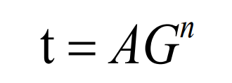
The empirical formula for calculating pouring time is given:
Where: T – pouring time (s), a – empirical coefficient, generally 2.5 ~ 3.5, taken as 2.5, G – total weight of metal in the mold (kg), taken as 26.8 kg, N – empirical coefficient, nodular cast iron taken as 0.33.
Taking the above values into equation 3-1, it is calculated that the casting time of nodular cast iron is 7.39 S. in order to prevent defects such as cold shut or insufficient pouring, the casting time is determined as 8 s according to the actual production demand.
② Calculation of average static head
According to the selection of nodular cast iron parting surface, the hub support is distributed in the upper and lower mold, and the molten iron is injected into the mold cavity from the middle part of nodular cast iron. According to the calculation formula:
Where: P – distance between the inflow position of inner gate and the top surface of nodular cast iron (m), H0 – sprue height (m), C – height of nodular cast iron at the pouring position (m), HP – average static head (m)
The height of nodular cast iron at the casting position is 125.3 mm, and the height of straight gate is the height of upper sand box, i.e. 220 mm. Bring into the above formula to calculate the average static head HP = 0.2 M.
③ Calculation of cross section size of each sprue
When determining the size and area of the gating system, it is generally necessary to first confirm the minimum flow blocking cross-sectional area in the system. The nodular cast iron gating system is semi closed, and the flow blocking cross-section is the inner gate area. According to the empirical formula of hydraulic principle, the sum of the inner gate cross-sectional area is:
Where: T – pouring time (s), μ— According to the process test and theoretical experience, the flow loss coefficient of the gating system is 0.43 in the wet mold, G – the total weight of the metal in the mold (kg), 26.8 kg, and HP – the average static head (m).
Bring the above relevant values into equation 3-3 and calculate that the sum of the minimum sectional area of the inner gate is 570 mm2. According to the determined section ratio relationship of semi closed gating system, determine a cross = 1248 mm2, a straight = 962mm2.
There are two nodular cast iron in type I. in order to ensure the filling effect, three internal sprues are set on both sides of nodular cast iron and in the middle of the two nodular cast iron. The introduction of molten metal from the thick wall is conducive to creating strong sequential solidification conditions and ensuring the sequential solidification of nodular cast iron from thin wall to thick wall and finally to riser. When there are multiple equal section ingates on the same runner, the flow of each ingate is different. In order to make the flow of each inner sprue uniform, the following measures should be taken in the design: first, make the sectional area of the inner sprue farther away from the straight sprue smaller, and design the transverse sprue as a tapered structure, that is, reduce the sectional area of the transverse sprue according to the ratio for each inner sprue. Secondly, a hemispherical gate nest is set at the lower end of the sprue to improve the head loss and local resistance at the corners of the sprue and transverse sprue.


