
Abstract:
The development process of ductile iron beam castings for high-precision gantry machining centers. Through comprehensive analysis of the structural characteristics and potential quality defects of beam castings, casting numerical simulation technology was utilized to optimize various process parameters. Strict control over raw material ratios, melting temperatures, spheroidization, and inoculation processes ensured high nodular graphite quality. After the initial trial production met technical requirements, further process improvements led to stable and consistent casting quality in mass production. This work provides guidance for producing other types of high-precision machine tool castings.
Keywords: ductile iron casting; beam castings; numerical simulation; process parameters; process control
1. Introduction
With the rapid development of industries such as aerospace, shipbuilding, automobiles, and energy equipment, the demand for high-precision machine tools, especially domestically produced ones, has become increasingly urgent. The improvement in the quality of machine tool castings plays a crucial role in the development of high-precision machine tools. This paper takes the ductile iron beam casting of a high-precision gantry machining center as an example to elaborate on the development process of large beam castings.
2. Casting Overview and Process Analysis
2.1 Structural Characteristics and Requirements
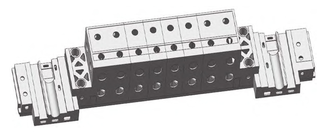
The beam is a vital structural component of a gantry machining center, requiring sufficient strength and stiffness to resist deformation and support gravity, which significantly impacts the machining accuracy of the machine tool. The material of choice for large machine tool beam castings is ductile iron. The beam casting developed by our company weighs 20 tons, with dimensions of 8,590 mm × 1,675 mm × 1,485 mm, a maximum wall thickness of 120 mm, and a minimum thickness of 30 mm. The material is QT600-3, with tensile strength ≥600 MPa, yield strength ≥370 MPa, elongation ≥3%, graphite nodularity grade 1-2, graphite size grade 6-7, pearlite content >70%, hardness of the guide rails 190-220 HBW, hardness difference controlled within 20 HBW, straightness of the guide rails ≤8 mm, and distance between the two end cylinders ±10 mm.
Table 1: Material Specifications of Beam Casting
| Specification | Value/Range |
|---|---|
| Material | QT600-3 |
| Tensile Strength (MPa) | ≥600 |
| Yield Strength (MPa) | ≥370 |
| Elongation (%) | ≥3 |
| Graphite Nodularity | Grade 1-2 |
| Graphite Size | Grade 6-7 |
| Pearlite Content (%) | >70 |
| Guide Rail Hardness | 190-220 HBW |
| Hardness Difference | ≤20 HBW |
| Guide Rail Straightness | ≤8 mm |
| Cylinder Distance | ±10 mm |
2.2 Casting Defect Analysis
Due to the beam’s long length and significant wall thickness variation, it is prone to deformation, shrinkage cavities, and porosity defects. Large processing脐子on the upper part can lead to slag inclusion and blowhole defects. Therefore, reasonable design of the pouring system, chillers, risers, slag-removal risers, and anti-deformation measures, combined with numerical simulation analysis to optimize the casting process, is essential to prevent casting defects.
3. Casting Process Design and Optimization
3.1 Parting Surface Selection
The selection of the parting surface should consider multiple factors such as casting dimensional accuracy, quality requirements of different parts, ease of operation, tooling conditions, and production efficiency. For machine tool castings, the guide rails are the most critical components, especially for high-precision machine tool castings, which must ensure the casting quality of the guide rails. Generally, the guide rails are placed on the bottom to ensure dense microstructure and reduce casting defects. Given the beam casting’s height and practical production conditions, a three-box molding method was chosen, with the parting surface. The guide rails and cylinders are in the lower box, the rest in the middle box, and the upper box serves as the cover, with a parting allowance of -2 mm.
3.2 Machining Allowance Selection
The beam casting adopts manual resin-bonded sand molding, with a maximum size of 8,590 mm. According to GB/T 6414-2017, the machining allowance grade is selected as G, and the casting dimensional tolerance grade is 11. The guide rails, auxiliary guide rails, and cylinders are critical parts with a machining allowance of 15 mm. To prevent porosity and slag inclusion defects after processing, the large processing脐子on the upper part also has a machining allowance of 15 mm, while the rest has a machining allowance of 13 mm.
Table 2: Machining Allowance Specifications
| Part | Machining Allowance (mm) |
|---|---|
| Guide Rails | 15 |
| Auxiliary Rails | 15 |
| Cylinders | 15 |
| Other Parts | 13 |
3.3 Static Solidification Simulation Analysis
Static solidification simulation analysis of the beam casting blank was conducted, assuming that all parts cool at the same temperature to predict potential defects. The simulation results showed that the rib plates and outer skin of the beam solidify first, while the guide rails, auxiliary guide rails, and cylinders solidify last, which are prone to shrinkage cavity and porosity defects. Therefore, chilling measures were taken at the last solidifying parts to accelerate the cooling rate of thick sections. Additionally, the upper processing cylinder surfaces showed shrinkage, indicating that the casting contracts as a whole under its own gravity, leading to shrinkage at the highest points. Thus, risers were placed at these locations for feeding.
3.4 Pouring System Design
A semi-closed bottom-pouring system was selected. The internal gate is throttled, the cross gate is enlarged, and the sprue remains full to prevent gas entrapment and allow slag to float on top of the cross gate, providing good slag retention capability. The internal gate position is at the end of the guide rail, ensuring smooth metal filling and avoiding splashing and oxidation, thereby guaranteeing the casting quality of the guide rail area.
3.5 Sand Core Design
The beam has a symmetrical structure, with the sand core mainly being the inner cavity sand core. When designing the sand core, attention was paid to both sand core strength and minimizing sand core segmentation and the use of core supports. The auxiliary guide rails at both ends of the beam are two-layer cores, divided into inner cavity cores and cover cores. The middle part has independent sand cores for each cavity, and the cylinder area has separate small cores fixed to the inner cavity cores through core heads.
3.6 Chiller and Riser Design
According to the static simulation results, the guide rails, auxiliary guide rails, and cylinders are the last to solidify, prone to shrinkage cavity and porosity defects, and require a dense microstructure for drilling. Therefore, chilled iron was placed to accelerate cooling. The thickness of the chilled iron is at least 0.3-0.8 times the diameter of the hot spot circle. Graphite chilled iron was used on the upper surface of the casting to prevent porosity at the contact surface between the chilled iron and the casting. Additionally, since the upper processing cylinder surfaces showed shrinkage, risers were placed there for liquid feeding and overflow slag removal.
3.7 Other Process Parameters
In the casting process of the crossbeam casting, besides the previously mentioned key process steps such as the selection of parting surfaces, the determination of machining allowance, static solidification simulation analysis, gating system design, sand core design, chill and riser design, there are also other important process parameters that need to be strictly controlled to ensure the quality of the casting.
Shrinkage Rate: During the casting process, due to the volumetric contraction of the molten metal as it cools and solidifies, the actual dimensions of the casting will be smaller than those of the mold. Therefore, a certain amount of shrinkage allowance needs to be reserved before casting. For this crossbeam casting, the shrinkage rate in the length direction is set at 1.2%, and that in the width and height directions is set at 1.0%. This parameter setting is based on the casting material, structural characteristics, and casting experience to ensure that the casting maintains the required dimensional accuracy after solidification.
Anti-deformation Allowance: Since the casting will undergo deformation during the cooling process, a certain amount of anti-deformation allowance needs to be preset before casting to offset or reduce the actual deformation of the casting. The anti-deformation allowance for this crossbeam casting is set at 12mm, which is determined based on comprehensive considerations of the casting’s structural characteristics, material properties, and stress distribution during the casting process. By presetting the anti-deformation allowance, the dimensional stability and processing accuracy of the casting can be significantly improved.
Holding Time and Unboxing Temperature: Holding time and unboxing temperature are important parameters that affect the internal structure and properties of the casting. A sufficient holding time can ensure that the internal structure of the casting is fully homogenized and reduce the occurrence of defects. The unboxing temperature needs to be controlled within a certain range to avoid deformation or cracking of the casting due to excessive temperature. For this crossbeam casting, the holding time is set at 160 hours, and the unboxing temperature is required to be below 280°C. This parameter setting is based on comprehensive considerations of the casting material, structure, and required properties.
3.8 Casting Process Simulation Analysis and Optimization
After the casting process design is completed, simulation analysis of the casting process is also required to verify and optimize the rationality of the process parameters. For this crossbeam casting, numerical simulation technology was used to simulate the filling and solidification processes.
Modeling and Simulation: Firstly, a three-dimensional model of the crossbeam was created based on the process design scheme. Then, casting simulation software was used to simulate the filling and solidification processes. During the simulation, simulation parameters that were as consistent as possible with the actual production control parameters were set to ensure the accuracy of the simulation results.
Simulation Result Analysis: The simulation results showed that during the filling process, the molten metal rose slowly and smoothly, with no obvious splashing phenomena. This is beneficial for avoiding defects such as gas entrapment and oxidation caused by excessive speed during the filling process. During the solidification process, the ingate solidified first, followed by the internal ribs and outer skin. Compared with static simulations, the cooling rate of the thick parts was significantly faster. The visible risers and insulating risers played a good role in feeding, and there was no sink mark on the casting after solidification.
However, the simulation results also revealed some potential issues. For example, the neck of the visible riser, which is in contact with the casting, solidified later, making it prone to porosity defects. To address this issue, adjustments need to be made to the size of the riser neck to optimize its feeding effect.
In summary, through casting process simulation analysis and optimization, potential defects in the casting process can be more accurately predicted, and adjustments and optimizations can be made to the process parameters accordingly. This helps improve the quality stability and production efficiency of the casting.