
I approach this development work as a practical foundry problem: a large bearing cover for a heavy-duty diesel engine must be produced as a sound ductile iron casting while maintaining dimensional accuracy, structural integrity, and economic yield. The component is thick and heavy, and the service load is cyclic and alternating. Therefore, the ductile iron casting must not only meet the nominal material grade but also satisfy strict local quality requirements around the main bolt holes. In my assessment, the central challenge is not simply pouring a large ductile iron casting; it is controlling the interaction among gating, filtration, solidification, graphite expansion, and chill-induced cooling so that shrinkage porosity and slag inclusion are displaced from critical regions.
The bearing cover outline is approximately 700 mm × 450 mm × 150 mm, with a rough casting weight near 190 kg. The specified material is QT400-15, which I treat as a ferritic ductile iron casting grade with high elongation and good toughness. The maximum wall thickness is about 150 mm, and the later machining operation forms the main bolt holes. Around those bolt holes, a zone of 10 mm must remain free of any defect. This requirement directly controls the process window, because the same region tends to become a thermal hot spot when the holes are not cast. The greater the hot spot, the greater the feeding demand; the greater the feeding demand, the more likely that a ductile iron casting will show shrinkage porosity unless the thermal field is redesigned.
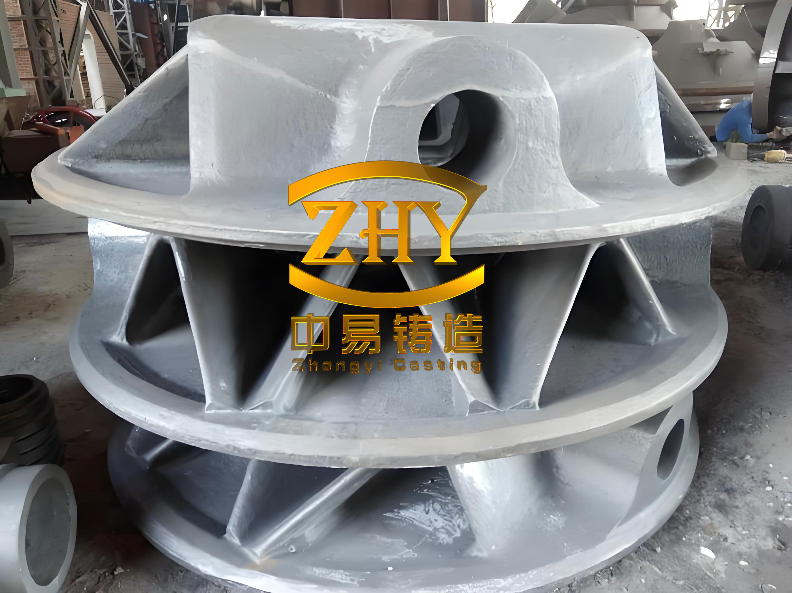
Initial technical targets. I summarized the component requirements in a form that could be used directly for process review. The important point is that the ductile iron casting must be evaluated as a system: material grade, geometry, defect-free zone, machining allowance, and production yield all interact. A process that improves one target can damage another. For example, adding risers may reduce shrinkage porosity but can reduce yield and create new hot spots. Adding filters may improve cleanliness but can disturb filling velocity if placed incorrectly.
| Item | Requirement | Process consequence |
|---|---|---|
| Component type | Large diesel engine bearing cover | Cyclic loading, high reliability demand |
| Outline size | 700 mm × 450 mm × 150 mm | Thick section, long feeding distance |
| Rough weight | Approximately 190 kg | High thermal mass, high pouring demand |
| Material | QT400-15 ductile iron casting | Graphite expansion can assist feeding |
| Maximum thickness | 150 mm | Slow cooling, large modulus, shrinkage risk |
| Bolt holes | Machined after casting in the initial route | Creates concentrated hot spot |
| Critical zone | 10 mm around each bolt hole without defects | Shrinkage and slag must be avoided locally |
In the original ductile iron casting route, the bolt holes were not cast. Instead, they were produced by later machining. The thick upper region was fitted with an insulating riser, while chills were placed on the lower side. I used a combination of riser and chill to reduce the risk of shrinkage porosity. Two ceramic filters were also installed to improve slag removal. This first ductile iron casting design had some logical advantages: it reduced the risk of insufficient material at the bolt holes, and it provided a feeding path from the upper riser. However, it also increased the effective hot spot volume. Because the bolt holes were left solid, the thermal center became larger and the feeding distance from the riser was limited. The result was an unresolved shrinkage porosity risk and a low casting yield.
| Original process feature | Design intention | Observed limitation |
|---|---|---|
| Bolt holes not cast | Avoid machining shortage and black skin | Increases hot spot volume and feeding demand |
| Insulating riser on thick upper section | Feed shrinkage during solidification | Feeding distance insufficient for large modulus |
| Chills on lower side | Promote directional cooling | Does not fully cover the hot spot |
| Two ceramic filters | Improve slag removal | Vertical placement reduced early filtration efficiency |
| Compact gating system | Reduce mold space and metal consumption | Short runner reduced slag settling and filter stabilization |
| Machined bolt holes | Ensure final dimensional accuracy | Critical zone remains exposed to dispersed porosity |
After cleaning, I found inclusion-type defects on the surface of the ductile iron casting. I examined the defects with electron microscopy and energy-dispersive analysis. The results showed a clear slag-related signature, with significant amounts of oxygen, silicon, calcium, aluminum, and zirconium, together with smaller amounts of sodium, magnesium, sulfur, manganese, and iron. This composition is consistent with a mixture of oxide inclusions, slag phases, and reaction products from the ceramic filter and mold environment. The presence of zirconium is especially useful as a tracer because it suggests that filter material or refractory interactions contributed to the inclusion population. In my view, the surface defects were not isolated events; they were symptoms of a gating and filtration system that did not stabilize quickly enough during the initial filling stage.
I also sectioned the casting and inspected the bolt-hole region. The section revealed dispersed cavity-like defects that I classified as shrinkage porosity. These defects were not large concentrated shrink holes; instead, they were distributed through the thick section. That morphology is typical of ductile iron casting solidification when feeding is incomplete and graphite expansion cannot fully compensate local volume contraction. The critical bolt-hole zone is particularly sensitive because it combines a large modulus, a late solidification time, and a strict defect-free requirement. A small amount of porosity that might be acceptable elsewhere becomes unacceptable near the bolt holes.
| Element | Weight percent | Atomic percent | Likely source |
|---|---|---|---|
| O | 49.17 | 71.32 | Oxide inclusions, slag |
| Na | 1.34 | 1.35 | Refractory or binder residue |
| Mg | 0.70 | 0.67 | Magnesium treatment products |
| Al | 3.34 | 2.87 | Oxide or deoxidation product |
| Si | 11.03 | 9.11 | Silicate slag, inoculation products |
| S | 0.79 | 0.57 | Sulfide inclusion |
| Ca | 11.26 | 6.52 | Slag former, refractory |
| Mn | 5.05 | 2.13 | Sulfide or alloy residue |
| Fe | 6.52 | 2.71 | Matrix and iron-rich phase |
| Zr | 10.82 | 2.75 | Filter or refractory tracer |
I then converted the defect analysis into a root-cause map. The first cause was the gating layout. The sprue and filter were placed too close together, and the runner length was short. A ceramic filter with straight holes cleans liquid metal mainly through mechanical interception, flow rectification, and filter-cake formation. If the filter is vertical and the initial flow is unstable, the filter cake does not develop uniformly. As a result, some inclusions pass through before the filter reaches its best operating condition. I expressed the filtration efficiency in a simple form:
$$ \eta_f = 1 – \frac{C_{\text{out}}}{C_{\text{in}}} $$
Here, \(C_{\text{in}}\) is the inclusion concentration entering the filter, and \(C_{\text{out}}\) is the concentration leaving it. The actual efficiency depends on residence time, flow velocity, particle size, and filter geometry. I also used a residence-time estimate:
$$ t_r = \frac{L_f}{v_f} $$
where \(L_f\) is the effective flow path through the filter and \(v_f\) is the local velocity. A short runner and a vertical filter reduce the stable residence time and create a transient start-up period during which filtration is poor. For a large ductile iron casting, the first metal entering the mold is often the dirtiest metal. If that metal reaches the critical surface before the filter stabilizes, slag defects appear.
The second cause was the thermal design. Leaving the bolt holes uncast produced a large hot spot. I estimated the thermal modulus of the thick region using the standard relationship:
$$ M = \frac{V}{A} $$
where \(M\) is the modulus, \(V\) is the volume, and \(A\) is the effective cooling surface area. For a simple plate-like section, the modulus approaches half the thickness:
$$ M \approx \frac{t}{2} $$
With a maximum thickness near 150 mm, the local modulus is large, and the solidification time is correspondingly long. Using Chvorinov’s rule:
$$ t_s = B M^n $$
where \(t_s\) is solidification time, \(B\) is a mold constant, and \(n\) is usually close to 2 for many castings. The larger the modulus, the later the section solidifies, and the more likely it is that shrinkage porosity will form if feeding is not adequate. A riser can feed only over a limited distance, especially in a heavy ductile iron casting where the graphite expansion effect is not uniformly distributed. The original riser was therefore not sufficient to guarantee soundness in the entire bolt-hole region.
| Root cause | Physical mechanism | Observed effect | Corrective direction |
|---|---|---|---|
| Short runner and compact gating | Insufficient slag settling and flow stabilization | Surface slag inclusion | Lengthen runner and reposition sprue |
| Vertical ceramic filter | Poor initial filter-cake formation | Early inclusions pass into mold | Horizontal filter with upward flow |
| Bolt holes not cast | Large hot spot and long solidification time | Dispersed shrinkage porosity | Cast holes with sand cores |
| Insulating riser only | Feeding distance too short for large modulus | Incomplete feeding | Conformal chills and graphite expansion |
| Partial chill coverage | Non-uniform cooling field | Late solidification pockets | Full hot-spot chill coverage |
| Low process yield | Large riser and excess metal | High cost per acceptable casting | Riser reduction and yield improvement |
Based on these findings, I changed the process in three main areas: the filtration system, the casting structure, and the cooling system. The revised ductile iron casting design was not a single change but an integrated thermal and fluid-flow solution. I wanted the liquid metal to enter the mold cleanly, pass through a stable filter, and then solidify under a controlled thermal gradient that uses graphite expansion while avoiding late hot spots near the bolt holes.
Filtration and gating revision. I moved the sprue to increase the runner length. The longer runner provides more distance for slag to separate and for flow to become more uniform before reaching the filter. I also changed the filter from a vertical orientation to a horizontal orientation. In the revised design, the liquid metal passes upward through the horizontal filter. This is important because upward flow through a horizontal filter promotes stable contact, reduces jetting, and allows a filter cake to form more uniformly. The filter then acts as a combined mechanical barrier, flow rectifier, and inclusion collector. I also adjusted the gating ratios so that the runner and ingates would not create excessive velocity at the filter. The general gating ratio can be written as:
$$ A_s : A_r : A_i : A_g $$
where \(A_s\), \(A_r\), \(A_i\), and \(A_g\) are the cross-sectional areas of the sprue, runner, filter inlet, and gate, respectively. In my revised ductile iron casting, I selected a more gradual reduction in area so that the filter was not overloaded at the start of pouring.
Casting structure revision. I decided to cast the bolt holes rather than leave them solid. This reduced the local hot spot dramatically. The bolt-hole cores were made with sufficient strength, and steel core rods were placed inside the sand cores to prevent core breakage and deformation. The core rods also helped maintain hole position during pouring. By casting the holes, I removed a large volume of late-solidifying metal from the critical zone. This lowered the thermal modulus, shortened the local solidification time, and reduced the amount of feeding required. In effect, I converted a large hot spot into a more uniform ring-like section with a smaller effective modulus.
Cooling system revision. I replaced the original riser-based feeding strategy with conformal chills covering the thick hot-spot regions. The chills were shaped to follow the casting contour, which improved contact and increased heat extraction. I applied the principles of equilibrium solidification: a ductile iron casting can use graphite expansion to compensate part of the shrinkage, but only if the thermal field is balanced. If some regions solidify too late, the expansion cannot compensate the remaining liquid contraction. The chills promote early skin formation and create a favorable thermal gradient. In my design, the chills provided initial feeding by accelerating solidification in the thick sections while the graphite expansion contributed internal self-feeding. A simplified expression for the expansion-assisted compensation is:
$$ V_{\text{sh}} \approx V_{\text{liq-cont}} – V_{\text{graphite-exp}} – V_{\text{feed}} $$
where \(V_{\text{sh}}\) is the residual shrinkage volume, \(V_{\text{liq-cont}}\) is liquid contraction, \(V_{\text{graphite-exp}}\) is graphite expansion, and \(V_{\text{feed}}\) is external feeding. The goal is to make \(V_{\text{sh}}\) as close to zero as possible in the critical zone. In practice, this requires a narrow window of carbon equivalent, inoculation, cooling rate, and chill placement.
| Improvement area | Original condition | Revised condition | Expected effect on ductile iron casting |
|---|---|---|---|
| Sprue position | Close to filter | Moved to lengthen runner | More slag settling and stable flow |
| Filter orientation | Vertical | Horizontal | Better filter-cake formation |
| Flow direction through filter | Lateral/unstable | Upward | Reduced jetting and improved capture |
| Bolt holes | Not cast | Cast with sand cores | Smaller hot spot, less porosity |
| Core reinforcement | Not specified | Steel core rods | Prevents core breakage and hole shift |
| Feeding | Insulating riser | Conformal chills | Faster local solidification |
| Chill coverage | Partial lower side | Full hot-spot coverage | More uniform thermal gradient |
| Solidification control | Riser-limited | Equilibrium solidification | Uses graphite expansion effectively |
I used MAGMA simulation to evaluate the revised ductile iron casting process. The simulation showed stable mold filling. The velocity fields were more uniform, and the filter did not show the same early bypass behavior. The thermal field after filling showed a reduced hot spot at the bolt-hole positions. The porosity prediction indicated a significant reduction in shrinkage tendency. I do not treat simulation as a replacement for trial casting, but in this case it helped confirm that the proposed changes were directionally correct. The simulation also helped me choose chill thickness and placement before cutting metal.
| Simulation output | Original process indication | Revised process indication | Interpretation |
|---|---|---|---|
| Filling stability | Moderate, local turbulence | Stable and progressive | Better filtration and less air entrapment |
| Filter approach velocity | High at start | Moderated | Improved filter-cake formation |
| Bolt-hole hot spot | Large, late solidification | Reduced and earlier | Lower shrinkage risk |
| Porosity tendency | Dispersed in critical zone | Greatly reduced | Critical zone protected |
| Thermal gradient | Non-uniform | More directional | Chills and cast holes work together |
| Yield prediction | Low due to riser | Higher with less feeding metal | Economic improvement |
After the simulation review, I carried out physical validation. Surface inspection of the revised ductile iron casting showed no obvious slag inclusion defects. I then sectioned representative castings and examined the bolt-hole region. The shrinkage porosity, where present, was located away from the bolt holes. The distance from the critical zone exceeded 76 mm, which satisfied the service requirement. This result was important because it showed that the process had not merely moved the defect to another visible location; it had shifted the last-solidifying region away from the bolt-hole area. In my interpretation, the combination of cast holes, conformal chills, and improved filtration changed the thermal and fluid history of the ductile iron casting in a favorable way.
| Validation item | Method | Result | Acceptance judgment |
|---|---|---|---|
| Surface slag | Visual inspection after cleaning | No obvious slag defects | Acceptable |
| Shrinkage porosity | Sectioning and visual examination | Located away from bolt holes | Acceptable |
| Distance from critical zone | Measurement after sectioning | Greater than 76 mm | Meets requirement |
| Bolt-hole integrity | Core and hole inspection | No breakage or deformation | Acceptable |
| Filling behavior | Simulation and trial pour | Stable and progressive | Acceptable |
| Small-batch trial | 20 castings | No shrinkage or slag defects | Problem effectively solved |
I then ran a small-batch validation of 20 pieces. All 20 ductile iron castings passed the surface and sectioning checks without shrinkage porosity or slag inclusion defects. The process yield increased from 56% to 82%. That increase is significant because it reduces the amount of returned metal, lowers remelting energy, shortens cleaning time, and improves delivery reliability. I calculate process yield as:
$$ Y = \frac{W_c}{W_c + W_r + W_g} \times 100\% $$
where \(W_c\) is the casting weight, \(W_r\) is the riser weight, and \(W_g\) is the gating system weight. In the original process, the large riser and heavy feeding system reduced \(Y\). In the revised process, the riser was replaced by conformal chills, and the gating system was made more efficient. As a result, \(W_r\) and \(W_g\) decreased, while the accepted casting weight remained essentially unchanged. The yield improvement is therefore a direct consequence of removing unnecessary metal from the mold.
| Metric | Original process | Revised process | Change |
|---|---|---|---|
| Casting yield | 56% | 82% | +26 percentage points |
| Slag defects | Observed on surface | Not observed in trial batch | Eliminated |
| Shrinkage porosity | Dispersed near bolt holes | Remote from bolt holes | Critical zone protected |
| Riser usage | Insulating riser | No large riser | Metal saving |
| Chill coverage | Partial | Conformal and full | Better thermal control |
| Filter placement | Vertical, short runner | Horizontal, longer runner | Better filtration |
| Batch validation | Not fully solved | 20 pieces accepted | Process capability confirmed |
Thermal and metallurgical reasoning. For a large ductile iron casting, I must control both the thermal modulus and the graphite expansion behavior. The carbon equivalent is a central variable. I used the following common relation for cast iron:
$$ CE = C + \frac{Si}{3} + \frac{P}{3} $$
For ductile iron casting, the target range should promote graphite precipitation and limit carbide formation. A carbon equivalent near the eutectic range helps increase graphite expansion and improves self-feeding. However, if the carbon equivalent is too high, graphite flotation and other defects can appear. If it is too low, shrinkage porosity and carbides become more likely. I therefore treat composition as a process window rather than a single value. The magnesium and rare-earth additions must be sufficient for spheroidization, but excessive residuals can increase slag and dross. Inoculation must be controlled to promote graphite nodules and avoid chill formation, especially in thin sections. In thick sections, the cooling rate is slower, so the nodule count and matrix may differ from thin sections. That is why the chill design and the chemical composition must be considered together.
| Variable | Role in ductile iron casting | Process direction | Risk if uncontrolled |
|---|---|---|---|
| Carbon | Graphite formation, expansion | Maintain within eutectic window | Shrinkage or graphite flotation |
| Silicon | Graphitization, ferrite promotion | Balance strength and elongation | Carbides or low toughness |
| Manganese | Matrix control, sulfide formation | Keep low for ferritic grade | Carbides, reduced elongation |
| Phosphorus | Low-melting phase formation | Keep low | Embrittlement, segregation |
| Sulfur | Magnesium consumption | Keep low before treatment | Poor spheroidization |
| Magnesium | Spheroidizing element | Sufficient but not excessive | Slag, dross, blowholes |
| Cerium/rare earths | Spheroidization assistance | Controlled residual | Dross and inclusions |
| Inoculant | Nucleation | Late and uniform addition | Chill, poor nodularity |
I also used thermal criteria to evaluate the revised ductile iron casting. The Niyama criterion is useful for predicting shrinkage porosity in castings:
$$ N = \frac{G}{\sqrt{\dot{T}}} $$
where \(G\) is the thermal gradient and \(\dot{T}\) is the cooling rate. A low Niyama value indicates a high tendency for shrinkage porosity. In the revised process, the conformal chills increase \(G\) and \(\dot{T}\) in the thick regions, which raises the local Niyama value and reduces the porosity risk. At the same time, casting the bolt holes reduces the local modulus and shortens the solidification time. The combination is more effective than either change alone. I also considered the thermal gradient directly:
$$ G = \frac{T_1 – T_2}{x} $$
where \(T_1\) and \(T_2\) are temperatures at two locations separated by distance \(x\). A strong positive gradient from the critical zone toward the chill promotes directional solidification. A flat or reversed gradient promotes isolated liquid pockets and dispersed porosity. The goal in the ductile iron casting is not necessarily to achieve a single global gradient but to ensure that the last liquid is not trapped in the bolt-hole region.
| Thermal criterion | Expression | Target in revised process | Effect on porosity |
|---|---|---|---|
| Modulus | \(M = V/A\) | Reduce near bolt holes | Lower feeding demand |
| Chvorinov time | \(t_s = B M^n\) | Shorten in critical zone | Earlier solidification |
| Niyama criterion | \(N = G/\sqrt{\dot{T}}\) | Increase locally | Less shrinkage porosity |
| Thermal gradient | \(G = (T_1 – T_2)/x\) | Direct toward chill | Directional feeding |
| Cooling rate | \(\dot{T} = dT/dt\) | Increase in thick sections | Finer structure, less porosity |
| Graphite expansion | \(V_{\text{graphite-exp}}\) | Promote self-feeding | Compensate liquid contraction |
| Residual shrinkage | \(V_{\text{sh}}\) | Approach zero | Sound ductile iron casting |
I modeled the feeding condition in a simplified way. If the liquid contraction before graphite expansion is \(V_{\text{liq-cont}}\), and the available expansion is \(V_{\text{graphite-exp}}\), then the external feeding required is:
$$ V_{\text{feed,req}} = V_{\text{liq-cont}} – V_{\text{graphite-exp}} + V_{\text{mold-wall}} $$
where \(V_{\text{mold-wall}}\) represents mold wall movement and other secondary effects. In a rigid mold, this term is small, but in a large ductile iron casting it cannot always be ignored. If \(V_{\text{feed,req}}\) is positive, a riser or chill-assisted feeding path is needed. If \(V_{\text{feed,req}}\) is negative, the expansion may be more than sufficient, but that can lead to other issues such as expansion defects. The optimum window is narrow. In my revised process, the chills help ensure that the expansion occurs while there is still a liquid channel, and the cast bolt holes reduce the volume of liquid that must be compensated.
Gating and filtration equations. I used several equations to guide the gating design. The flow rate through the gate is:
$$ Q = A_g v_g $$
where \(Q\) is volumetric flow rate, \(A_g\) is gate area, and \(v_g\) is gate velocity. If the gate velocity is too high, mold erosion and turbulence increase. If it is too low, cold shuts and misruns can occur. For a large ductile iron casting, the filling time must be short enough to avoid cold metal but long enough to avoid severe turbulence. The filter pressure drop can be approximated as:
$$ \Delta P = \frac{\mu v L}{K} + \rho g h $$
where \(\mu\) is viscosity, \(v\) is velocity, \(L\) is filter thickness, \(K\) is permeability, \(\rho\) is density, \(g\) is gravity, and \(h\) is metal head. A horizontal filter with upward flow changes the pressure distribution and helps the filter cake form evenly. The longer runner also increases the path length before the filter:
$$ L_{\text{runner}} = L_{\text{total}} – L_{\text{sprue}} – L_{\text{gate}} $$
By increasing \(L_{\text{runner}}\), I gave inclusions more time to float or settle before they reached the critical mold cavity. The slag removal effect is not infinite, but in combination with the filter it produced a cleaner ductile iron casting.
| Gating variable | Symbol | Original tendency | Revised direction |
|---|---|---|---|
| Sprue-to-filter distance | \(L_{sf}\) | Short | Increased |
| Runner length | \(L_{\text{runner}}\) | Short | Longer |
| Filter orientation | — | Vertical | Horizontal |
| Flow direction through filter | — | Lateral | Upward |
| Filter efficiency | \(\eta_f\) | Unstable at start | More stable |
| Gate velocity | \(v_g\) | Potential local spikes | Moderated |
| Inclusion settling | \(t_r\) | Short | Longer |
| Slag defect risk | — | Higher | Lower |
Chill and cooling design. I placed conformal chills over the thick hot spots instead of using a large riser. The chills were designed to follow the casting contour because a conformal contact reduces the air gap and improves heat transfer. The heat flux through the chill can be described qualitatively by:
$$ q = h_c (T_c – T_m) $$
where \(q\) is heat flux, \(h_c\) is the contact heat-transfer coefficient, \(T_c\) is the casting surface temperature, and \(T_m\) is the chill temperature. A larger \(h_c\) and a larger temperature difference increase heat extraction. The chill must be thick enough to absorb heat without melting or overheating, but not so thick that it causes excessive chilling, carbides, or cracking. In my process, the chill size and spacing were chosen so that the critical bolt-hole region solidified earlier than the surrounding feeding path. This created a thermal gradient toward the chill and away from the critical zone.
| Chill parameter | Selection principle | Reason |
|---|---|---|
| Material | High thermal diffusivity | Fast heat extraction |
| Shape | Conformal to casting contour | Good contact and uniform cooling |
| Thickness | Sufficient heat capacity | Avoid chill saturation |
| Placement | Directly at thick hot spots | Reduce local modulus |
| Coverage | Full hot-spot coverage | Avoid isolated late liquid pockets |
| Coating | Controlled to prevent sticking | Clean surface and safe knockout |
| Chill check | Inspect for erosion and fit | Repeatable process |
| Solidification effect | Earlier skin formation | Less shrinkage porosity |
I also used a simple heat-balance estimate for the chill. If the casting section has mass \(m_c\), specific heat \(c_p\), and latent heat \(L_f\), and the chill has mass \(m_{ch}\) and specific heat \(c_{ch}\), then the approximate temperature rise of the chill is:
$$ \Delta T_{ch} = \frac{m_c (c_p \Delta T_c + L_f f_s)}{m_{ch} c_{ch}} $$
where \(f_s\) is the solid fraction at the time of interest. This estimate is not a full simulation, but it helps avoid undersized chills. For a large ductile iron casting, an undersized chill may heat up too quickly and stop extracting heat before the hot spot has solidified. An oversized chill may cause local chilling and carbide formation. I therefore combined the estimate with MAGMA simulation and trial validation.
Core design for cast bolt holes. Casting the bolt holes required strong sand cores. I placed steel core rods inside the sand cores to prevent breakage and deformation. The core must withstand metal pressure, buoyancy, and thermal shock. The buoyant force on a core can be estimated as:
$$ F_b = \rho_m g V_{\text{displaced}} $$
where \(\rho_m\) is the density of liquid metal and \(V_{\text{displaced}}\) is the displaced volume. If the core is not properly supported, this force can shift the core and cause wall-thickness variation. The steel core rods increase stiffness and help maintain position. I also ensured that the core prints and chaplets were adequate. After casting, the cores were removed cleanly, and the bolt-hole positions were within tolerance. This change not only reduced the hot spot but also reduced machining allowance and improved material utilization.
| Core design item | Function | Quality benefit |
|---|---|---|
| Sand core | Forms bolt hole | Reduces hot spot |
| Steel core rod | Reinforces core | Prevents breakage and distortion |
| Core print | Supports and locates core | Maintains hole position |
| Venting | Removes core gas | Prevents blowholes |
| Coating | Improves surface finish | Reduces cleaning and machining |
| Knockout | Removes core after cooling | Prevents damage to casting |
| Dimensional check | Verifies hole location | Ensures bolt-hole tolerance |
Quality control plan. For a ductile iron casting of this size and duty, I established a quality control plan that included chemical analysis, microstructure checks, surface inspection, sectioning, and dimensional verification. The critical bolt-hole zone was checked by sectioning during development. In production, I used a combination of process monitoring and sampling. The most important variables were melt chemistry, magnesium treatment, inoculation, pouring temperature, pouring time, filter condition, chill placement, and core positioning. I treated each of these variables as part of the ductile iron casting process window. If one variable moves outside its range, the risk of shrinkage porosity or slag inclusion increases.
| Control item | Method | Frequency | Critical limit |
|---|---|---|---|
| Carbon equivalent | Thermal analysis or spectrometer | Every heat | Within eutectic window |
| Magnesium residual | Spectrometer | Every heat | Sufficient for nodularity |
| Inoculation | Late addition control | Every pour | Uniform and sufficient |
| Pouring temperature | Pyrometer | Every pour | Within specified range |
| Pouring time | Timer or operator record | Every pour | Short enough to avoid cold shut |
| Filter condition | Visual before pouring | Every mold | No cracks or misalignment |
| Chill placement | Visual check | Every mold | Conformal and secure |
| Core position | Gauge or visual | Every mold | No shift or breakage |
| Surface quality | Visual after cleaning | Every casting | No slag or visible defects |
| Sectioned porosity | Sectioning | Development and audit | Critical zone defect-free |
In my first-person assessment, the small-batch result is the strongest evidence that the revised ductile iron casting process is capable. The original process produced slag inclusion and dispersed shrinkage porosity, and the yield was only 56%. The revised process produced no defects in 20 consecutive castings and raised yield to 82%. The critical zone was protected, and the last-solidifying region moved away from the bolt holes by more than 76 mm. I do not consider this a purely local fix; it is a process philosophy for heavy ductile iron casting: reduce the hot spot by design, clean the metal before it enters the cavity, and control the thermal field so that graphite expansion and chill cooling work together.
Economic and production effects. The yield increase from 56% to 82% has a direct economic effect. I can express the metal cost per acceptable casting as:
$$ C_{\text{acc}} = \frac{C_{\text{melt}} + C_{\text{mold}} + C_{\text{post}}}{Y} $$
where \(C_{\text{melt}}\) is melting cost, \(C_{\text{mold}}\) is molding cost, \(C_{\text{post}}\) is cleaning and finishing cost, and \(Y\) is yield. Because \(Y\) increased, the cost per acceptable ductile iron casting decreased. In addition, fewer defects mean less rework, less scrap, and less disruption to machining. The cast bolt holes reduce machining allowance and avoid the risk of black skin in the holes. The conformal chills replace a large riser, which saves liquid metal and reduces remelting. The horizontal filter and longer runner improve cleanliness, which reduces surface repair. All of these effects reinforce each other.
| Economic factor | Original process | Revised process | Effect |
|---|---|---|---|
| Yield | 56% | 82% | Less returned metal |
| Riser weight | High | Low or eliminated | Melting energy saving |
| Gating weight | Moderate to high | Optimized | Better metal utilization |
| Slag repair | Frequent | Rare in trial | Lower labor cost |
| Porosity scrap | Risk near bolt holes | Reduced | Higher acceptance |
| Machining allowance | Higher due to solid holes | Lower due to cast holes | Less machining |
| Process stability | Marginal | Improved | Better delivery reliability |
Generalized process window. I summarize the main variables of this large ductile iron casting in a process window table. The values are not universal constants; they are the direction of control that I found effective. The key is that each variable must be held within a range. A single variable outside the range can cause shrinkage porosity or slag inclusion even if the others are correct.
| Variable | Role | Target direction | Failure mode if missed |
|---|---|---|---|
| Carbon equivalent | Graphite expansion | Eutectic window | Shrinkage or flotation |
| Inoculation | Nucleation | Late and uniform | Chill or poor nodularity |
| Magnesium residual | Spheroidization | Sufficient, not excessive | Slag or poor graphite shape |
| Pouring temperature | Fluidity and shrinkage | Controlled range | Cold shut or shrinkage |
| Pouring time | Filling stability | Short but not turbulent | Cold shut or mold erosion |
| Runner length | Slag settling | Increased | Inclusion defects |
| Filter orientation | Filtration | Horizontal | Early inclusion bypass |
| Filter flow direction | Flow stability | Upward | Jetting and filter bypass |
| Bolt-hole cores | Hot-spot reduction | Cast holes | Large hot spot and porosity |
| Core reinforcement | Core stability | Steel rods | Core breakage or shift |
| Chill placement | Cooling control | Conformal and full | Late liquid pocket |
| Chill thickness | Heat capacity | Sufficient | Chill saturation |
Analytical summary. I can express the overall improvement as a combined defect-risk function:
$$ R_{\text{defect}} = f(R_{\text{slag}}, R_{\text{shrink}}, R_{\text{thermal}}, R_{\text{core}}) $$
where \(R_{\text{slag}}\) is the slag inclusion risk, \(R_{\text{shrink}}\) is the shrinkage porosity risk, \(R_{\text{thermal}}\) is the thermal imbalance risk, and \(R_{\text{core}}\) is the core-related risk. In the original process, \(R_{\text{slag}}\) and \(R_{\text{shrink}}\) were both high. In the revised process, the longer runner and horizontal filter reduced \(R_{\text{slag}}\), while the cast bolt holes and conformal chills reduced \(R_{\text{shrink}}\) and \(R_{\text{thermal}}\). The steel core rods reduced \(R_{\text{core}}\). The result was a robust ductile iron casting process with higher yield and better quality. I also note that the improvement is not simply additive; the changes interact. For example, a cleaner metal supply helps the chill-controlled solidification because fewer inclusions interfere with heat transfer and feeding. A smaller hot spot helps the filter because less metal must be fed through the critical zone. A better thermal gradient helps graphite expansion because the expansion occurs while the feeding path is still open.
| Risk category | Original level | Revised level | Main control |
|---|---|---|---|
| Slag inclusion | High | Low | Longer runner, horizontal filter |
| Shrinkage porosity | High | Low | Cast bolt holes, conformal chills |
| Thermal imbalance | High | Low | Full hot-spot chill coverage |
| Core failure | Moderate | Low | Steel core rods |
| Low yield | High | Low | Riser reduction, gating optimization |
| Machining risk | Moderate | Low | Cast holes and controlled allowance |
Final conclusions from my work. The development of this large ductile iron casting showed that slag inclusion and shrinkage porosity can be addressed together when the gating system and the solidification system are designed as one. I found that a longer runner and a horizontally placed filter with upward flow significantly improve slag removal. I also found that casting the bolt holes with reinforced sand cores reduces the hot spot and lowers the shrinkage risk near the critical zone. Replacing the original riser strategy with conformal chills and applying equilibrium solidification principles allows the ductile iron casting to use graphite expansion more effectively. The simulation and trial results supported these changes. In the small-batch validation, 20 ductile iron castings showed no shrinkage or slag defects, and the process yield increased from 56% to 82%. I therefore consider the revised process to be a practical and repeatable solution for this type of heavy ductile iron casting.
For future work, I would continue to monitor the process window, especially carbon equivalent, inoculation, pouring temperature, filter condition, and chill fit. I would also maintain sectioning audits around the bolt-hole region because that zone defines the acceptance of the ductile iron casting. The experience confirms that a large ductile iron casting is not made sound by one isolated measure. It is made sound by aligning metal cleanliness, thermal gradients, feeding, graphite expansion, and core integrity. When these factors are aligned, the ductile iron casting achieves the required mechanical properties, the critical zone remains defect-free, and the foundry obtains a higher yield with lower processing cost.