Firstly, from the aspect of changing the height of nodular cast iron pouring riser, without changing the diameter and neck size of nodular cast iron pouring riser, only increase the height of nodular cast iron pouring riser to – scheme 1: HR = 70 mm, HR side = 90 mm and scheme 2: HR = 80 mm, HR side = 100 mm.
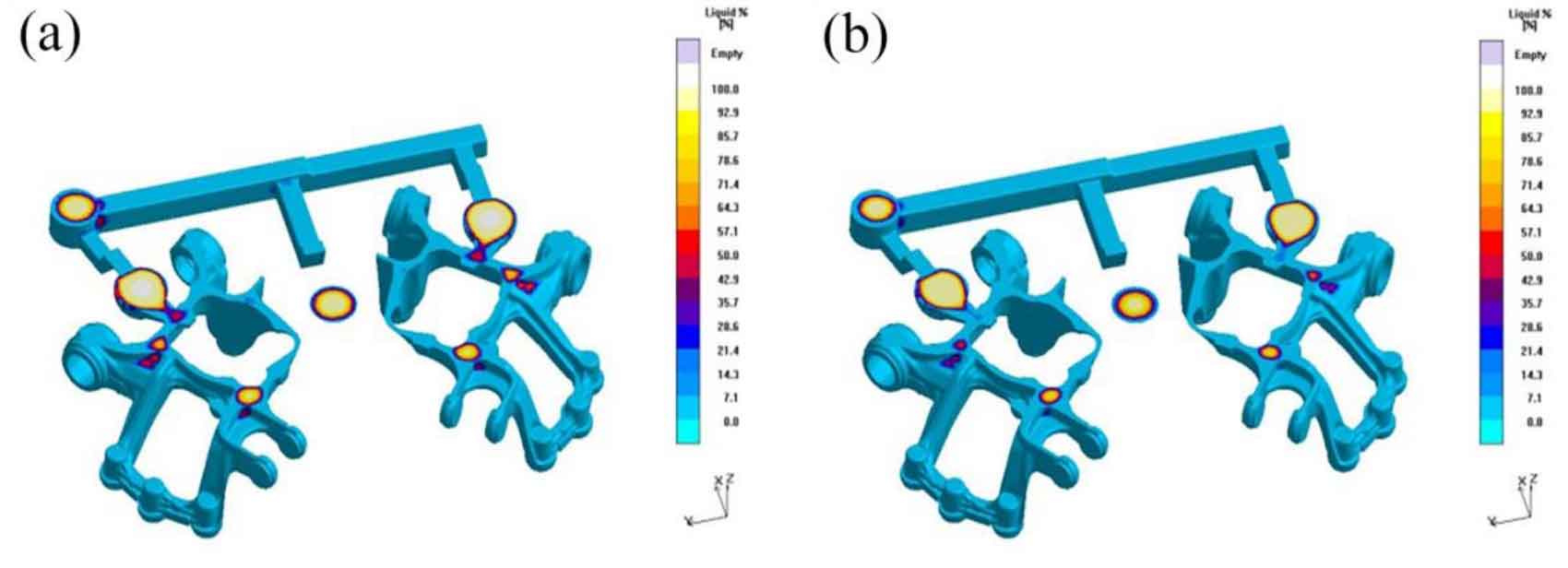
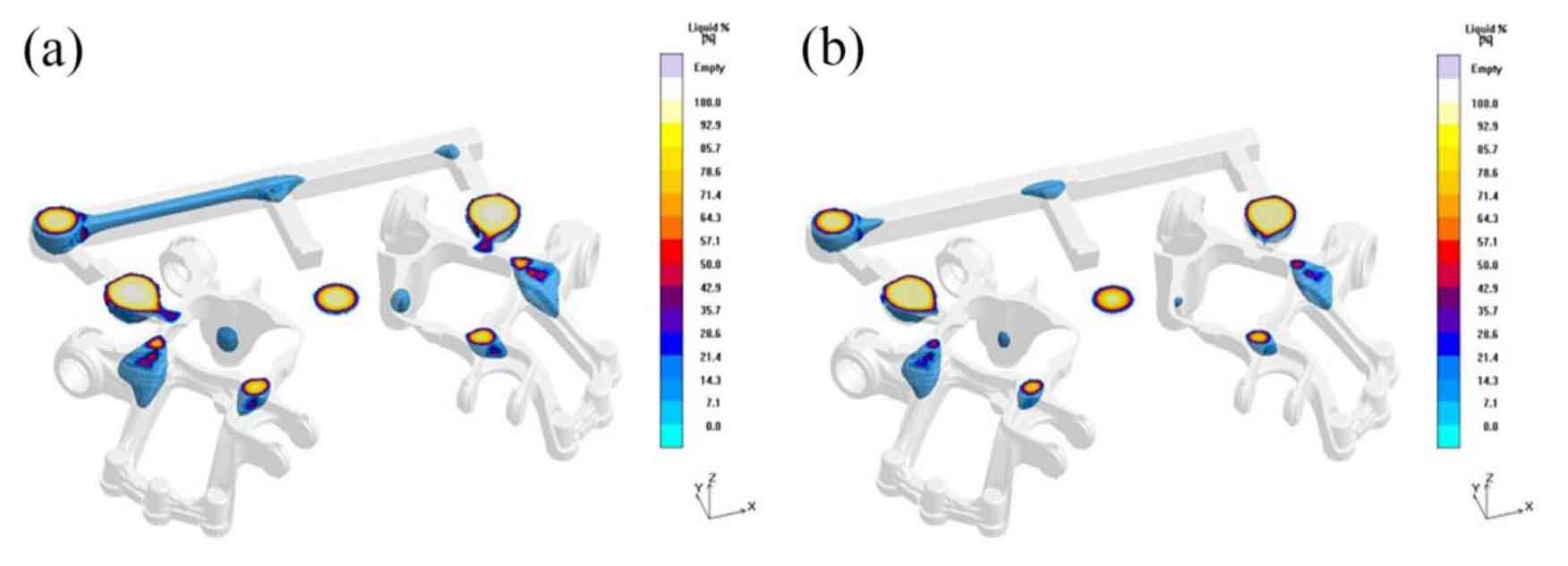
Fig. 1 and Fig. 2 are the nephogram of liquid phase rate distribution in the later solidification stage of nodular cast iron pouring riser improvement scheme 1 and scheme 2 respectively. It can be seen from the figure that with the increase of the height of nodular cast iron pouring riser, the feeding time of nodular cast iron pouring riser is further extended to 191.33 s and 195.17 s, indicating that the feeding effect of nodular cast iron pouring riser is enhanced compared with the original scheme.
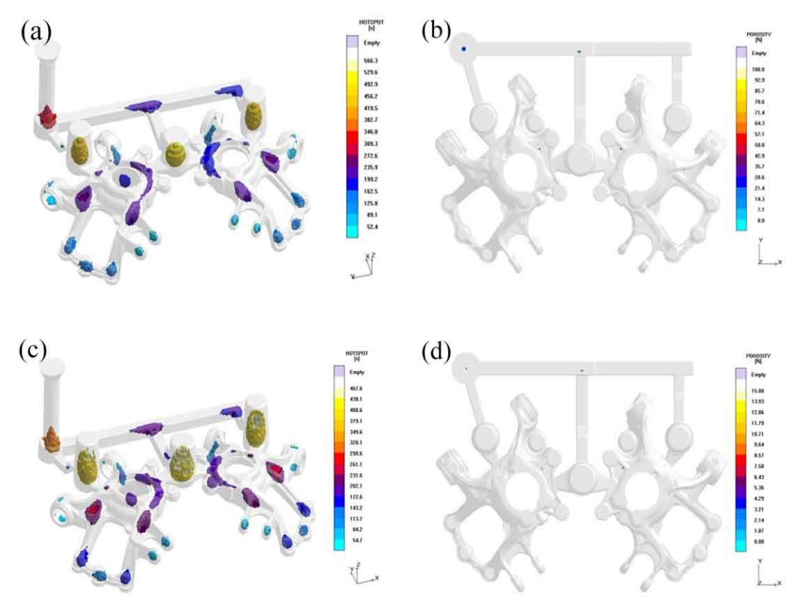
The hot spot distribution results and shrinkage cavity distribution results after the simulation calculation of the two groups of improved schemes are shown in Figure 3. It can be seen intuitively that the shrinkage distribution area is still mainly concentrated on both sides of the middle riser, but the number is slightly reduced compared with the original scheme before the improvement. According to figure 3 (a) and (c), the two groups of improved nodular cast iron pouring risers improve the continuous large hot spots previously distributed in the thick part above the nodular cast iron close to the side riser, so that the hot spot area is reduced or dispersed into discontinuous small hot spots. Among them, scheme 1 has a better effect on the improvement of thermal section. In scheme 2, because the height of the pouring riser of nodular cast iron is too high, a new contact heat joint is generated on the nodular cast iron (Fig. 3 (c)), which may lead to a new isolated liquid phase area, which is not conducive to the improvement of the quality of nodular cast iron. Therefore, the height of the pouring riser of nodular cast iron designed in scheme 1 is more reasonable.