
Combating persistent blowhole defects in complex, thin-walled cast iron cylinder heads, particularly for heavy-duty truck engines, remains a significant challenge within the foundry industry. This article details practical solutions developed through extensive trial production for a representative six-cylinder head, characterized by its large size (883mm x 340mm x 133mm), minimal wall thickness (δ = 5mm), weight (110kg), and HT250 material specification. Initial production using wet green sand molds (formed via squeeze molding) and hot-box cured resin-coated sand cores, arranged horizontally in a one-casting-per-mold configuration, consistently yielded unacceptable blowhole defects concentrated on the oil pan rail face.
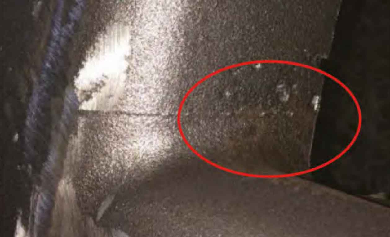
Initial trials revealed blowhole defects primarily clustered at the extreme ends of the oil pan rail face (designated Areas A and B in the structural illustration below) and on specific bosses (Areas C and D). Analysis identified these as predominantly blowhole defect types: dissolved gas porosity (majority) and some minor subsurface blows in A/B, with dissolved gas porosity dominating in C/D. The severity and distribution evolved during different trial phases, pointing to specific process deficiencies.
Root Cause Analysis of Blowhole Formation
Thorough investigation attributed the persistent blowhole defect issues to several interconnected factors related to gating, core materials, mold permeability, and metal quality:
- Suboptimal Gating Leading to Adverse Thermal Gradients:
- Initial Side Gating (Medium Pouring): Trials using central gating systems feeding from either the intake or exhaust manifold side (Scheme 1 & 2 in Figure 2 schematic) resulted in an inverse temperature gradient within the mold cavity – cooler metal at the top (oil pan rail) and hotter metal at the bottom. This profile severely hindered the buoyant escape of gases from the solidifying metal upwards towards the oil pan rail face, directly contributing to pervasive subsurface blows and dissolved gas porosity across the entire surface. The thermal profile can be represented by:
$$\frac{\partial T}{\partial z} < 0 \quad \text{(during critical solidification stage)}$$
where \(T\) is temperature and \(z\) is the vertical coordinate (positive upwards). - Unbalanced Top Gating: Switching to a top-gating system via modified riser necks (Scheme 3 in Figure 2 schematic) improved the overall thermal gradient direction (\(\frac{\partial T}{\partial z} > 0\)), favoring gas venting upwards. However, improper sizing led to gross imbalance: the total choke cross-sectional area (\(\Sigma F_{\text{choke}}\)) was significantly smaller than the total ingate area (\(\Sigma F_{\text{inner}}\)). This caused excessive metal flow into the central cavity region, creating a “hot center – cold ends” thermal profile:
$$T_{\text{center}} \gg T_{\text{ends}}$$
This imbalance starved the ends (Areas A, B) of sufficient thermal mass, hindering dissolved gas diffusion and bubble floatation, leading to concentrated blowhole defect formation in these regions and on the adjacent bosses (C, D).
- Initial Side Gating (Medium Pouring): Trials using central gating systems feeding from either the intake or exhaust manifold side (Scheme 1 & 2 in Figure 2 schematic) resulted in an inverse temperature gradient within the mold cavity – cooler metal at the top (oil pan rail) and hotter metal at the bottom. This profile severely hindered the buoyant escape of gases from the solidifying metal upwards towards the oil pan rail face, directly contributing to pervasive subsurface blows and dissolved gas porosity across the entire surface. The thermal profile can be represented by:
- Inappropriate Water Jacket Core Sand Properties: Water jacket cores, due to their large surface area and confinement, are major gas sources. Trials using finer-grained (50/100 mesh) resin-coated sand with high gas evolution (>15 mL/g) significantly increased the gas load within the core cavity during pouring and solidification, overwhelming the venting capacity and directly contributing to blowhole defect formation, particularly near the core surface.
- Inadequate Mold and Core Ventilation: The mold configuration placed the entire casting in the drag (bottom flask), resulting in an excessively tall cope (top flask). Combined with low permeability (< 150) in the backing sand, this created significant resistance to gas evacuation from the deep cope and from the cores, trapping gases that subsequently invaded the metal or impeded dissolved gas escape.
- Poor Metal Quality: Using cupola-melted base iron without adequate treatment resulted in inherently high levels of dissolved gases (notably hydrogen and nitrogen) and suspended oxides/slags. These provided nucleation sites for bubble formation (dissolved gas porosity) and could react to generate additional gases, directly feeding the blowhole defect problem. The gas solubility difference between liquid and solid iron drives porosity formation:
$$C_{\text{liquid}} > C_{\text{solid}}$$
where \(C\) is the gas concentration. Excess initial gas content (\(C_{\text{initial}}\)) exacerbates this.
Key Process Modifications for Blowhole Reduction
Based on the root cause analysis, targeted process changes were implemented to systematically address the blowhole defect challenge:
1. Optimized Gating System Design
The transition from side gating to top gating was crucial but required refinement.
- Top Gating Implementation: Adopting a top-gating scheme (Scheme 3, Fig. 2) fundamentally reversed the thermal gradient to a favorable \(\frac{\partial T}{\partial z} > 0\) state, promoting natural buoyancy-driven gas migration towards the top surface and potential escape paths.
- Ingate/Choke Area Balancing: The critical step involved rigorously balancing the metal flow. The total cross-sectional area of the ingates (riser necks converted to ingates) was reduced to match the choke area:
$$\Sigma F_{\text{inner}} = \Sigma F_{\text{choke}}$$
This ensured uniform filling and a more consistent thermal profile (\(T_{\text{center}} \approx T_{\text{ends}}\)) throughout the cavity, eliminating the cold spots at the ends that were prone to blowhole defect formation. Balanced flow minimizes localized premature solidification blocking gas escape paths.
Table 1: Impact of Gating System Modifications on Blowhole Defect Incidence
| Gating Scheme | Thermal Gradient Direction | Flow/Temperature Uniformity | Observed Blowhole Severity | Primary Blowhole Locations |
|---|---|---|---|---|
| Side Gating (Medium Pouring) | \(\frac{\partial T}{\partial z} < 0\) (Adverse) | Moderate | Severe (100% Baseline) | Entire Oil Rail Face |
| Unbalanced Top Gating | \(\frac{\partial T}{\partial z} > 0\) (Favorable) | Poor (Hot Center, Cold Ends) | Significant Reduction (20-30% of Baseline) | Oil Rail Ends (A,B), Bosses (C,D) |
| Balanced Top Gating (\(\Sigma F_{\text{inner}} = \Sigma F_{\text{choke}}\)) | \(\frac{\partial T}{\partial z} > 0\) (Favorable) | Good (Uniform Profile) | Major Reduction (>90% Reduction) | Sporadic Minor Defects (Controllable) |
2. Optimization of Water Jacket Core Sand
Selecting the correct resin-coated sand for the high-gas-volume water jacket cores was vital.
- Coarser Grain Size: Sand with a primary grain distribution of 40/70 mesh was specified instead of 50/100 mesh. Coarser grains inherently increase the core’s intrinsic permeability (\(k\)), facilitating better internal gas venting:
$$k \propto d^2$$
where \(d\) is the effective grain diameter. - Reduced Gas Evolution: Sand with a maximum gas evolution of 15 mL/g was mandated. Lower gas evolution (\(G_{\text{evol}}\)) directly reduces the total gas load (\(V_{\text{gas}}\)) released into the core cavity during pouring:
$$V_{\text{gas}}} = m_{\text{sand}}} \times G_{\text{evol}}}$$
where \(m_{\text{sand}}}\) is the sand mass in the core.
Table 2: Resin-Coated Sand Properties for Water Jacket Cores
| Sand Property | Problematic Condition | Optimized Condition | Impact on Blowhole Defect |
|---|---|---|---|
| Primary Grain Size (Mesh) | 50/100 (Finer) | 40/70 (Coarser) | Increased Permeability, Improved Internal Venting |
| Gas Evolution (mL/g) | > 15 (Higher) | ≤ 15 (Lower) | Reduced Total Gas Load from Core |
| Core Permeability (Typical) | Lower | Higher | Faster Escape of Core Gases |
3. Enhanced Mold and Core Venting
Improving the escape routes for gases generated from the sand binders and cores was essential.
- Mold Permeability Increase: The permeability of the backing sand was increased and maintained within a range of 150-200. Permeability (\(P\)) is a key indicator of a mold’s ability to transmit gases:
$$P = \frac{V \times h}{A \times t \times p}$$
where \(V\) is the air volume (cm³), \(h\) is the sample height (cm), \(A\) is the sample cross-section (cm²), \(t\) is the time (min), and \(p\) is the air pressure (gf/cm²). Higher \(P\) reduces back pressure buildup. - Strategic Venting: Five to six additional vent holes (Ø12-16mm) were drilled into the cope (tall upper flask) at strategic locations directly above core prints and cavity high points. These provided low-resistance paths for gases accumulating in the deep cope and escaping from cores to exit the mold, preventing pressurization that could force gas into the metal causing a blowhole defect.
4. Metal Treatment for Quality Improvement
Addressing the inherent gas content and cleanliness of the cupola iron was critical.
- Gas Purification (“NC” Treatment): 0.05% of a proprietary “NC” purifying agent was added to the base iron during tapping or in the transfer ladle. This agent promotes agglomeration and flotation of suspended oxides and facilitates the removal of dissolved gases (denoting primarily hydrogen removal efficiency, \(\eta_{\text{H}}\)), thereby reducing nucleation sites and dissolved gas concentration (\(C_{\text{initial}}\)):
$$\Delta C_{\text{H}}} = C_{\text{initial,H}}} – C_{\text{final,H}}} = f(\text{“NC” dosage, treatment time})$$ - Inoculation & Secondary Purification: 0.3-0.4% Rare Earth Silicon (RE-Si) alloy (approx. 30% RE, 40% Si) was added for inoculation. Beyond improving graphite morphology and mechanical properties (enhancing strength and hardness), RE elements have a strong affinity for oxygen and sulfur, providing a secondary cleansing effect:
$$2[\text{RE}] + 3[\text{O}] \rightarrow \text{RE}_2\text{O}_3\text{(slag)}$$
$$2[\text{RE}] + 3[\text{S}] \rightarrow \text{RE}_2\text{S}_3\text{(slag)}$$
This further reduces the potential for gas-forming reactions (e.g., \(C + O \rightarrow CO\), \(C + FeO \rightarrow CO + Fe\)) at the metal-mold interface or within the melt, mitigating a potential source for blowhole defect formation.
Table 3: Metal Treatment Impact on Blowhole Reduction Mechanisms
| Treatment | Dosage | Primary Function | Secondary Function | Impact on Blowhole Defect |
|---|---|---|---|---|
| “NC” Purifier | 0.05% | Dissolved Gas Removal (\(\downarrow C_{\text{initial}}}\)) | Slag Inclusion Reduction | Reduces Nucleation Sites & Gas Content |
| RE-Si Inoculant | 0.3-0.4% | Graphite Modification, Strength Increase | Deoxidation, Desulfurization | Reduces Oxide/Sulfide Inclusions, Suppresses Gas-Forming Reactions |
Conclusion
The persistent and costly blowhole defect problem in wet sand casting of large, complex heavy-duty truck cylinder heads was successfully overcome through a systematic, multi-faceted approach. The synergistic implementation of a balanced top-gating system, optimized coarse-grained low-gas resin-coated sand for critical cores, enhanced mold permeability coupled with strategic venting, and rigorous metal treatment (purification and inoculation) proved highly effective. The balanced top gate ensured a favorable thermal gradient and uniform solidification. Optimized core sand minimized gas generation and maximized venting within the core itself. Improved mold venting provided efficient escape paths for all generated gases. Finally, metal purification and treatment significantly reduced the dissolved gas content and nucleation sites within the iron itself.
This comprehensive set of process modifications transformed the production status of these challenging castings. The incidence of blowhole defect was reduced to levels acceptable for consistent, high-quality serial production, moving beyond the problematic trial phase. The solutions outlined provide a validated technical framework applicable to mitigating similar gas-related defects in other complex, thin-section iron castings produced via green sand molding. The focus on controlling thermal gradients, gas generation sources, venting efficiency, and metal quality offers a robust strategy for foundries facing the persistent challenge of blowholes.