
In modern manufacturing, the demand for materials that combine excellent mechanical properties with good manufacturability and cost-effectiveness is ever-present. Among these, spheroidal graphite iron (often referred to as ductile iron) stands out as a critical engineering material. Its unique microstructure, characterized by spherical graphite nodules embedded in a ferrous matrix, grants it a remarkable combination of strength, toughness, and damping capacity, surpassing that of conventional gray cast iron. Consequently, spheroidal graphite iron has found widespread application in demanding components such as engine blocks, cylinder heads, crankshafts, camshafts, and various heavy-duty industrial parts. However, this very microstructure also presents distinct challenges during machining, placing specific demands on cutting tool performance. The graphite nodules, while improving ductility, can act as discontinuities that influence chip formation and tool wear mechanisms, making the selection of optimal tool geometry paramount for achieving efficiency, surface quality, and economic viability.
This article presents a comprehensive investigation into the influence of rake face groove geometry—specifically the configuration of cutting edge preparation, angles, and chip breaker forms—on the cutting performance of indexable turning inserts when machining spheroidal graphite iron. Through systematic experimental analysis of cutting forces, progressive wear, and resistance to interrupted cutting, we aim to elucidate the critical relationships between tool micro-geometry and machining outcomes for this important material.
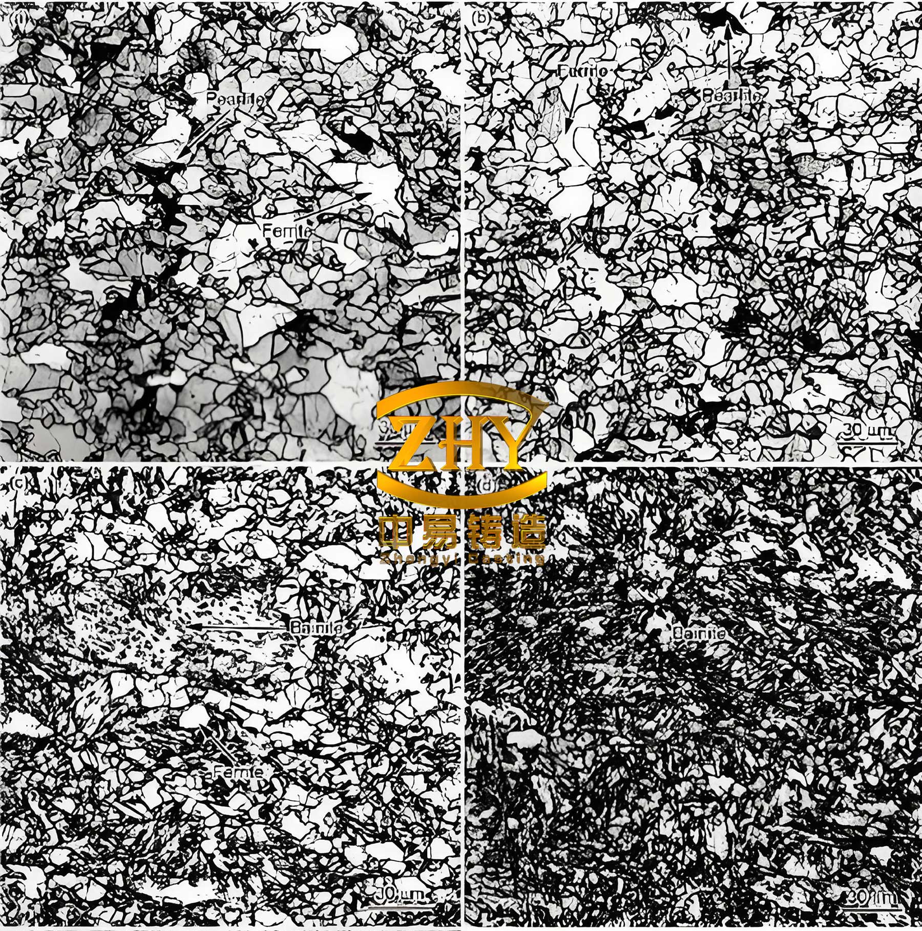
Material Characteristics and Machining Challenges of Spheroidal Graphite Iron
The grade of spheroidal graphite iron examined in this study is a ferritic-pearlitic grade with a nominal tensile strength of 500 MPa. Its chemical composition and key mechanical properties are summarized in Table 1. The presence of magnesium as a nodulizing agent ensures the spherical formation of graphite, which is central to its properties.
| Element | Content (wt.%) |
|---|---|
| Carbon (C) | 3.55 – 3.85 |
| Silicon (Si) | 2.34 – 2.86 |
| Manganese (Mn) | < 0.60 |
| Magnesium (Mg) | 0.02 – 0.04 |
| Sulfur (S) | < 0.025 |
| Phosphorus (P) | < 0.08 |
| Iron (Fe) | Balance |
Table 1: Chemical composition of the spheroidal graphite iron workpiece material.
| Property | Value |
|---|---|
| Tensile Strength | 500 MPa |
| Yield Strength | 320 MPa |
| Hardness (Brinell) | 170 – 230 HB |
| Elongation | 7% |
Table 2: Mechanical properties of the spheroidal graphite iron workpiece material.
The machining behavior of spheroidal graphite iron is a hybrid of that observed in ductile steels and brittle cast irons. The ferritic/pearlitic matrix allows for some plastic deformation during chip formation, while the graphite nodules facilitate chip breaking and provide solid lubrication at the tool-chip interface, potentially reducing friction and heat generation. However, this lubrication is inconsistent, and the nodules also create a micro-interrupted cutting action that can accelerate notch wear at the depth-of-cut line. Furthermore, the abrasive nature of the pearlitic phase and the constant micro-impacts from the graphite can lead to combinations of abrasive, adhesive, and fatigue wear on the cutting tool. Therefore, optimizing the tool’s geometry to manage cutting forces, control chip flow, and enhance edge strength is crucial for productive machining of spheroidal graphite iron.
Experimental Methodology and Tool Geometry Analysis
The experimental work was conducted on a high-power CNC lathe capable of maintaining stable cutting conditions. A three-component piezoelectric dynamometer was mounted between the tool holder and the machine turret to measure the cutting force components (main cutting force \( F_c \), feed force \( F_f \), and passive/radial force \( F_p \)) in real-time. All machining tests were performed under dry conditions to clearly observe the fundamental interaction between the tool and the spheroidal graphite iron, without the cooling or lubricating effects of cutting fluid.
The core of this study involves the evaluation of three distinct D-style (55° rhombus) indexable turning inserts, designated here as Insert A, Insert B, and Insert C. All inserts share an identical substrate composition (92% tungsten carbide, 8% cobalt) and a similar multilayer hard coating, isolating the geometric features of the rake face as the primary variable. The detailed geometry of each insert’s cutting edge and rake face groove was meticulously characterized using optical profiling and surface measurement systems. The critical extracted parameters are presented in Table 3.
| Insert Designation | First Rake Angle (\( \gamma_o \)) | Cutting Edge Inclination (\( \lambda_s \)) | Honed Edge Land Width (\( b_{\gamma} \)) |
|---|---|---|---|
| Insert A | 12.24° | +3.00° | 0.230 mm |
| Insert B | 8.10° | 0.00° | 0.199 mm |
| Insert C | 10.01° | 0.00° | 0.206 mm |
Table 3: Key cutting edge geometry parameters for the three tested inserts.
The First Rake Angle (\( \gamma_o \)) is the primary angle that defines the slope of the rake face immediately behind the cutting edge. It directly influences shear plane mechanics and cutting forces. The Cutting Edge Inclination (\( \lambda_s \)) is the angle the cutting edge makes relative to the reference plane. A positive \( \lambda_s \) tilts the cutting edge such that the tip is the lowest point, influencing chip flow direction, edge strength, and entry conditions. The Honed Edge Land Width (\( b_{\gamma} \)) refers to a small, flat or slightly rounded section (a micro-bevel or T-land) ground onto the cutting edge after the primary and secondary rake angles are formed. This land acts as a reinforced negative chamfer, significantly increasing the edge’s robustness and resistance to chipping and wear, especially important for the abrasive and intermittent nature of machining spheroidal graphite iron.
The experimental plan consisted of three phases:
- Cutting Force Analysis: Continuous turning tests to establish baseline force data for each insert under stable conditions.
- Tool Wear Investigation: Extended duration tests to monitor the progression of flank wear and identify wear mechanisms.
- Impact Resistance Testing: Interrupted cutting tests using a workpiece with axial slots to simulate severe mechanical shocks and evaluate tool life under dynamic loading.
The common cutting parameters for these tests were: Cutting Speed \( V_c = 200 \, \text{m/min} \), Feed Rate \( f = 0.15 \, \text{mm/rev} \), and Depth of Cut \( a_p = 2.0 \, \text{mm} \).
Analysis of Cutting Forces as a Function of Rake Angle
The measured main cutting force (\( F_c \)) for the three inserts, under identical cutting conditions, revealed a clear and significant trend. Insert B, with the smallest first rake angle of 8.10°, generated the highest cutting force. Insert C, with a 10.01° rake angle, produced a moderately lower force. Insert A, featuring the largest rake angle of 12.24°, consistently demonstrated the lowest cutting force.
This result can be fundamentally explained by the mechanics of orthogonal cutting and the Lee and Shaffer shear angle relationship. According to their simplified model, the shear angle \( \phi \) is related to the tool rake angle \( \gamma_o \) and the average friction angle \( \beta \) at the tool-chip interface:
$$ \phi = \frac{\pi}{4} – \beta + \gamma_o $$
An increase in the positive rake angle \( \gamma_o \) leads to an increase in the shear angle \( \phi \). A larger shear angle implies a thinner shear plane and a smaller shear area. Since the force required for plastic deformation is directly proportional to the area of the shearing region, the cutting force decreases. This relationship holds true for spheroidal graphite iron within a practical range. While a very large positive rake angle would excessively weaken the cutting edge, particularly against the abrasive components of the material, the results confirm that in the range of approximately 8° to 12°, selecting a larger positive first rake angle is an effective strategy for reducing the energy consumption and mechanical load during the machining of spheroidal graphite iron. The reduction in \( F_c \) also implies lower power requirements and potentially reduced process-induced stresses in the workpiece.
The dependency of the main cutting force \( F_c \) on the rake angle can be further approximated for this specific material and test range by a linear fit. From the experimental data, we can model:
$$ F_c(\gamma_o) \approx k_1 – k_2 \cdot \gamma_o $$
where \( k_1 \) and \( k_2 \) are positive constants derived from the specific workpiece-tool combination. For spheroidal graphite iron QT500-7 and this class of carbide tools, a higher \( \gamma_o \) within the 10°-15° window reliably yields a lower \( F_c \).
Wear Performance and the Role of the Cutting Edge Land
Given their lower cutting forces, Inserts A and C were selected for a comparative wear study. The progression of flank wear land width (\( VB \)) over machining time was recorded. The industry-standard failure criterion for finishing operations, \( VB = 0.3 \, \text{mm} \), was used as a key reference point.
The wear curves revealed a critical difference. While both inserts exhibited an initial period of rapid wear followed by a more stable period, Insert C reached the \( VB = 0.3 \, \text{mm} \) limit in approximately 180 seconds. In contrast, Insert A operated well beyond this point, exhibiting a more gradual wear progression and a significantly longer time to reach an equivalent or greater wear level. Post-test examination of the flank faces under high magnification provided further insight. Insert C showed signs of more pronounced abrasion and localized adhesive material transfer (built-up edge tendencies), whereas Insert A’s wear scar was more uniform and controlled.
The dominant factor explaining this superior wear resistance of Insert A is its wider honed edge land (\( b_{\gamma} = 0.230 \, \text{mm} \) vs. \( 0.206 \, \text{mm} \) for Insert C). When the insert is mounted in the holder, this land functions as a dedicated, strong negative chamfer at the very cutting edge. It provides several key benefits when machining spheroidal graphite iron:
- Increased Edge Strength: It reduces the effective sharpness and stress concentration at the micron level, preventing micro-chipping caused by the constant micro-impact from the hard graphite nodules and pearlite colonies.
- Improved Heat Dissipation: The larger cross-sectional area at the edge improves conduction of heat away from the cutting zone, mitigating thermal softening of the substrate.
- Wear Reserve: The land itself constitutes a volume of hard substrate and coating material that must be worn away before the geometry of the primary rake face is significantly altered. It acts as a sacrificial buffer.
The relationship between wear rate and edge land width can be conceptualized. The volumetric wear rate \( \dot{V}_w \) is often related to the acting pressure and sliding distance. A stronger edge (from a larger \( b_{\gamma} \)) maintains its geometry longer under abrasive conditions, effectively reducing the rate of increase of the flank wear land \( VB \):
$$ \frac{d(VB)}{dt} \propto \frac{1}{f(b_{\gamma})} $$
where \( f(b_{\gamma}) \) is an increasing function of the edge land width, representing its reinforcing effect. Therefore, for the abrasive wear mechanisms prevalent in machining spheroidal graphite iron, a moderately wider edge land is a highly effective design feature for extending tool life, even if it comes at a marginal potential cost of slightly increased cutting forces compared to an infinitely sharp edge.
Impact Resistance and the Significance of Positive Cutting Edge Inclination
The final and perhaps most demanding test evaluated the tool’s performance under interrupted cutting conditions, which are common when machining parts with keyways, slots, or uneven surfaces in spheroidal graphite iron. This subjects the cutting edge to cyclic mechanical and thermal shocks.
In this impact test, Insert A demonstrated a dramatically longer life than Insert C. Insert A sustained over 51,000 impacts before reaching a defined failure criteria, whereas Insert C failed after approximately 37,000 impacts. This represents nearly a 40% increase in impact resistance for Insert A. The surface roughness generated by Insert A was also marginally better at the end of its longer test, indicating more stable edge condition throughout.
The decisive geometric differentiator here is the positive cutting edge inclination (\( \lambda_s = +3^\circ \)) of Insert A, compared to the neutral (\( \lambda_s = 0^\circ \)) geometry of Insert C. A positive \( \lambda_s \) provides crucial advantages in an interrupted cut:
- Progressive Engagement: As the rotating workpiece brings the cutting edge into contact, a positive \( \lambda_s \) ensures that the contact begins at a point away from the tool tip and gradually proceeds towards it. This avoids an instantaneous full-width shock load on the weakest part of the corner radius.
- Altered Force Vector: The positive inclination angle alters the direction of the resultant cutting force, directing it more into the thicker, more supportive part of the insert’s body, improving its ability to withstand bending moments.
- Enhanced Edge Strength Compensation: A fundamental rule of thumb in tool design states that increasing the positive rake angle (\( \gamma_o \)) to reduce forces can be effectively counterbalanced by introducing a corresponding positive inclination angle (\( \lambda_s \)) to maintain edge strength. Insert A employs this principle perfectly: its larger \( \gamma_o \) (12.24°) is paired with a positive \( \lambda_s \) (+3°). This combination allows it to reap the benefits of lower cutting forces during stable cutting phases while having the structural integrity to survive the repeated impacts encountered when machining spheroidal graphite iron components with interruptions.
The impact energy \( E_{imp} \) absorbed by the cutting edge per engagement can be considered proportional to the product of the force and the engagement dynamics. A positive \( \lambda_s \) smoothens the engagement impulse \( I \):
$$ I = \int F(t) \, dt $$
where the force function \( F(t) \) has a less abrupt onset. This reduces peak stress and the propensity for fatigue crack initiation at the cutting edge, a common failure mode in interrupted cutting of spheroidal graphite iron.
Synthesis and Practical Implications for Machining Spheroidal Graphite Iron
The experimental findings coalesce into a coherent framework for selecting and designing tool geometries for optimal machining of spheroidal graphite iron. The interactions between the key geometric parameters—first rake angle (\( \gamma_o \)), edge land width (\( b_{\gamma} \)), and cutting edge inclination (\( \lambda_s \))—must be balanced to meet specific machining objectives, whether they prioritize low force, maximum wear life, or supreme toughness.
For stable, continuous finishing operations on spheroidal graphite iron, where minimizing deflection and achieving fine surface finish are priorities, a tool geometry with a relatively larger positive first rake angle (12°-15°) and a moderate to narrow edge land is advantageous. This configuration minimizes cutting forces and power consumption.
For heavy roughing or operations where abrasive wear is the primary life-limiting factor, such as turning large-diameter spheroidal graphite iron castings with sand inclusions, the emphasis should shift. A slightly reduced rake angle (8°-12°) coupled with a significantly wider honed edge land will provide the necessary wear resistance and edge security to achieve reliable, predictable tool life.
For any operation involving interruptions—milling, turning slotted shafts, or facing across cast webs—the inclusion of a positive cutting edge inclination (3° to 5°) becomes critical. As demonstrated, this feature can dramatically increase tool life in such conditions. It is perfectly compatible with a positive rake angle; in fact, they should be specified together. A useful design guideline is to increase \( \lambda_s \) by 2° to 3° for every 2° increase in \( \gamma_o \) beyond a baseline neutral configuration to maintain equivalent edge strength for dynamic loads.
The optimization of these geometric parameters interacts with other tooling factors. For instance, a tougher substrate grade can allow for a slightly larger effective rake angle or a narrower land. Advanced coatings with high hardness and low friction further synergize with an optimized geometry to protect the edge from both abrasive and adhesive wear when machining spheroidal graphite iron.
Conclusion
This detailed investigation into the effects of rake face geometry on the machining performance of spheroidal graphite iron yields definitive and actionable conclusions. The three-dimensional contour of the cutting edge and chip groove is not merely a chip-breaking device but a fundamental variable controlling the mechanical, thermal, and dynamic interaction between the tool and workpiece.
- The first rake angle (\( \gamma_o \)) is the primary geometric factor influencing cutting force. For machining spheroidal graphite iron grades like QT500-7, operating within a first rake angle range of 10° to 15° and selecting the larger feasible angle within this window is an effective strategy for reducing the main cutting force, lowering power consumption, and minimizing process-induced stresses.
- The width of the honed cutting edge land (\( b_{\gamma} \)) is paramount for wear resistance. When machining the abrasive microstructure of spheroidal graphite iron, a wider land acts as a reinforced negative chamfer, significantly enhancing the edge’s resistance to abrasive and adhesive wear mechanisms, thereby extending stable tool life, especially in continuous cutting operations.
- The cutting edge inclination angle (\( \lambda_s \)) is the critical factor for impact resistance. A positive inclination angle (+3° or more) fundamentally improves the tool’s ability to withstand the mechanical shocks inherent in interrupted cutting of spheroidal graphite iron. It facilitates smoother engagement, directs forces favorably, and compensates for the potential edge-weakening effect of a large positive rake angle, leading to a dramatic increase in tool life under dynamic loading conditions.
Ultimately, the successful and efficient machining of spheroidal graphite iron demands a holistic approach to tool selection, where the substrate, coating, and geometry are matched to the specific operation. The insights provided here underscore that a carefully engineered rake face geometry, balancing a sufficiently positive rake angle for low force, a robust edge land for wear resistance, and a positive inclination for toughness, is essential for unlocking the full productivity potential when working with this versatile and challenging engineering material.