
In this comprehensive account, we detail our firsthand experience in manufacturing a massive ductile iron casting platform, a critical component for heavy-duty machinery. The production of such large-scale ductile iron castings presents significant challenges, particularly concerning graphite degeneration, shrinkage defects, and ensuring uniform mechanical properties throughout thick sections. Our goal was to develop a reliable and efficient process to meet stringent technical specifications for a 110-ton platform. The entire process, from design to inspection, was meticulously planned and executed, with a focus on the unique requirements of heavy-section ductile iron casting.
The platform, with its complex internal ribbing and varying wall thicknesses, demanded a holistic approach to casting science. The successful implementation hinged on integrating robust gating design, precise metallurgical control, and advanced solidification simulation. This article will systematically explore the casting process, chemical composition design, melting and treatment procedures, and the final quality verification, all centered around the core objective of producing a high-integrity ductile iron casting.
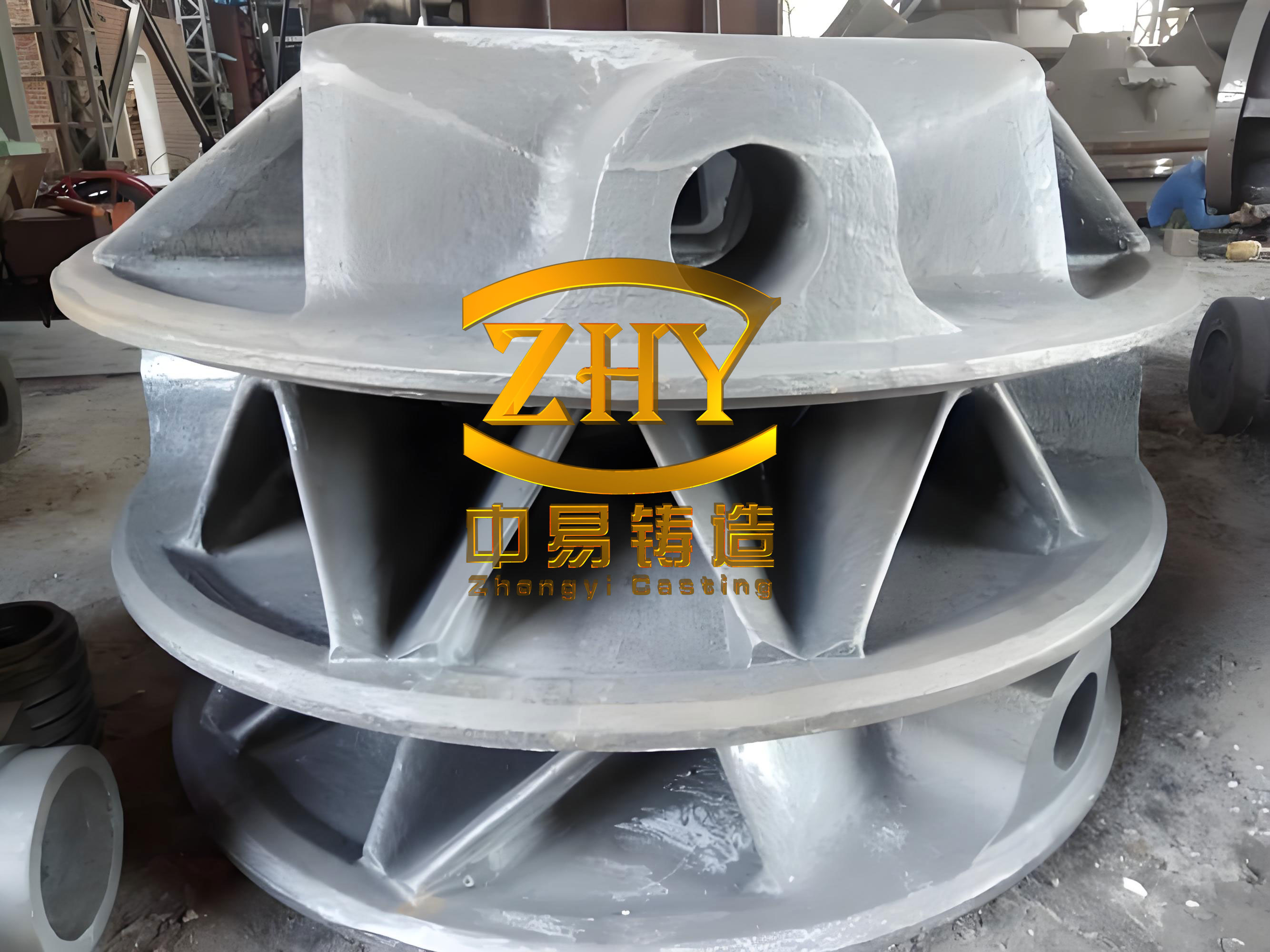
The casting process for a large ductile iron casting begins with a thorough design phase. For this platform, we employed a three-part molding system using core assembly within a molding pit. This method is economically viable and offers superior safety for handling such massive molds. The primary machining surfaces were oriented downward to maximize quality. To account for potential dimensional shifts during solidification of a large ductile iron casting, strategic machining allowances were applied to the non-machined sides of critical faces. The mold material was phenolic-modified furan resin no-bake sand, coated with alcohol-based paints. The coating thickness was varied according to the local section thickness of the ductile iron casting to control the cooling rate and metal-mold interaction.
The gating system is paramount for the quality of any ductile iron casting, especially a large one. We designed a bottom-gating, unpressurized (open) system to ensure a calm and rapid fill. The system consisted of multiple downsprue, runner, and ingate components assembled from ceramic tubes. The total cross-sectional area ratio was carefully calculated: ΣAingate : ΣArunner : ΣAdownsprue = 4.1 : 2.3 : 1. Ingates were distributed around the perimeter of the casting to introduce metal evenly and minimize temperature gradients. A slag-trapping basin was incorporated to reduce dross entrainment. The simulation of this ductile iron casting process was performed using ProCAST software to predict and eliminate shrinkage porosity. The simulation results, visualized as a fraction solid or Niyama criterion plot, confirmed that the designed risers and chills effectively directed shrinkage into the risers, leaving the casting body sound. The governing equation for heat transfer during solidification of a ductile iron casting is the Fourier heat conduction equation, coupled with the release of latent heat:
$$ \rho C_p \frac{\partial T}{\partial t} = \nabla \cdot (k \nabla T) + \rho L \frac{\partial f_s}{\partial t} $$
where $ \rho $ is density, $ C_p $ is specific heat, $ T $ is temperature, $ t $ is time, $ k $ is thermal conductivity, $ L $ is latent heat, and $ f_s $ is the solid fraction. This model was crucial for optimizing the placement of chills and risers in our large ductile iron casting.
Chills were extensively used in regions of high thermal modulus to promote directional solidification. Exothermic risers were placed atop the casting to provide adequate feed metal. The effectiveness of a chill can be related to its chilling power, which for a ductile iron casting can be approximated by its ability to extract heat. The heat extracted $ Q $ by a chill can be estimated by:
$$ Q = \int_{0}^{t} h A (T_{cast} – T_{chill}) \, dt $$
where $ h $ is the interfacial heat transfer coefficient, $ A $ is the contact area, and $ T $ denotes temperatures. Proper use of chills is vital to prevent shrinkage in thick sections of a ductile iron casting.
| Element | Target Range (wt.%) | Primary Influence on Ductile Iron Casting |
|---|---|---|
| Carbon (C) | 3.5 – 3.9 | Enhances graphite precipitation, fluidity, and self-feeding. High levels risk graphite flotation. |
| Silicon (Si) | 2.0 – 2.3 | Promotes graphitization, strengthens ferrite, but increases brittle transition temperature. |
| Manganese (Mn) | ≤ 0.3 | Minimized to prevent carbide formation and segregation at grain boundaries. |
| Sulfur (S) | ≤ 0.02 | Kept low to reduce Mg and RE consumption during spheroidization. |
| Phosphorus (P) | ≤ 0.04 | Minimized to avoid phosphide eutectic formation and cold cracking. |
| Magnesium (Mg) | 0.04 – 0.06 (Residual) | Essential for graphite spheroidization. Excess increases shrinkage tendency. |
| Rare Earth (RE) | 0.01 – 0.03 (Residual) | Aids in desulfurization and spheroidizing. Excess promotes chunky graphite. |
The chemistry of a ductile iron casting is the foundation of its microstructure and properties. For this heavy-section ductile iron casting, carbon equivalent (CE) is a critical parameter. While the formula $ CE = C + \frac{Si}{3} $ is common for gray iron, for ductile iron casting we focus on absolute levels to balance fluidity and graphite morphology. High carbon increases the number of graphite nodules, which can be beneficial. The number of graphite nodules per unit area $ N_v $ influences the mechanical properties; a higher count generally refines the matrix and improves ductility. An empirical relationship for yield strength in ferritic ductile iron casting can be considered:
$$ \sigma_y \approx \sigma_0 + k_y (N_v)^{-1/2} $$
where $ \sigma_0 $ and $ k_y $ are material constants. Silicon content was controlled to achieve a fully ferritic matrix after solidification and heat treatment, as required for high elongation. The detrimental effects of manganese and phosphorus are exacerbated in slow-cooling sections of a large ductile iron casting due to microsegregation, governed by the Scheil equation approximation:
$$ C_s = k C_0 (1 – f_s)^{k-1} $$
where $ C_s $ is the solute concentration in the solid, $ C_0 $ is the initial concentration, $ k $ is the partition coefficient, and $ f_s $ is the solid fraction. This underscores why low levels of segregating elements are mandatory for heavy-section ductile iron casting.
The melting and treatment process for this ductile iron casting was executed with precision. The charge consisted of 80% high-purity pig iron (low in Si, Mn, S) and 20% selected steel scrap. Carburizer was added to achieve the target carbon. Melting was conducted in medium-frequency induction furnaces. After melting, the iron was superheated to 1500–1530°C and held for 5-10 minutes to dissolve impurities and reduce genetic inheritance from the charge materials. The tapping temperature was controlled between 1420–1460°C. Pre-inoculation with silicon-barium was performed in the ladle before tapping to provide nucleation sites.
The spheroidization treatment for this ductile iron casting was performed using the wire feeding method. This process involves injecting a cored wire containing magnesium and rare earth alloys into the molten iron. Compared to the traditional sandwich method, wire feeding offers superior control over residual magnesium, reduced temperature loss, lower slag generation, and a cleaner working environment. The reaction efficiency, or magnesium recovery $ \eta_{Mg} $, can be defined as:
$$ \eta_{Mg} = \frac{Mg_{residual}}{Mg_{added}} \times 100\% $$
The wire feeding method typically achieves a more consistent and higher $ \eta_{Mg} $ for large ductile iron casting production. For our platform, a high-magnesium cored wire of 13 mm diameter was used at a controlled feed rate. Multiple ladles were treated simultaneously to minimize temperature differences between them. Immediately after treatment, the metal surface was covered with rice husk ash for slag aggregation and insulation.
Inoculation is critical to counteract fading in large ductile iron casting. We employed a composite, multi-stage inoculation practice. Post-inoculation was done using a 13 mm diameter ferrosilicon cored wire injected during transfer. A final, late-stream inoculation was achieved by placing preheated ferrosilicon blocks in the pouring basin. This practice aims to maintain a high nucleation rate throughout solidification. The fading of inoculation effect over time $ t $ can be modeled as a decrease in active nuclei density $ N $:
$$ \frac{dN}{dt} = -k_f N $$
where $ k_f $ is a fading rate constant. Multiple inoculation events help replenish $ N $, ensuring a fine graphite structure in the final ductile iron casting.
| Process Stage | Parameter | Value or Range |
|---|---|---|
| Melting | Superheating Temperature | 1500 – 1530 °C |
| Melting | Holding Time at Superheat | 5 – 10 minutes |
| Tapping | Tapping Temperature | 1420 – 1460 °C |
| Wire Feeding | Spheroidizing Wire Diameter | 13 mm |
| Wire Feeding | Inoculating Wire Diameter | 13 mm |
| Processing Window | Time from Treatment to Pouring | < 25 minutes |
| Pouring | Pouring Temperature | 1330 – 1360 °C |
Pouring of the ductile iron casting was a carefully orchestrated operation. A dam-type pouring basin was used, which served a dual purpose: agitating the metal to float out slag and acting as a secondary slag trap. The pouring temperature was maintained within a narrow range to balance fluidity and minimize shrinkage defects. The pouring sequence followed a “slow-fast-slow” pattern to ensure a smooth fill without turbulence. The gating system’s design ensured a rising metal front in the mold cavity. At the end of the pour, the basin was topped up multiple times to compensate for liquid shrinkage and ensure adequate feeding from the risers. The total solidification time $ t_s $ for such a large ductile iron casting can be estimated using Chvorinov’s rule:
$$ t_s = B \left( \frac{V}{A} \right)^n $$
where $ V $ is volume, $ A $ is cooling surface area, $ B $ is a mold constant, and $ n $ is an exponent (typically ~2 for sand castings). For our platform, this time was substantial, requiring the mold to be left undisturbed for an extended period.
After solidification, the ductile iron casting was allowed to cool in the mold to below 300°C before shakeout. This practice minimizes the development of residual stresses $ \sigma_{res} $, which are related to the thermal gradient $ \nabla T $ and the coefficient of thermal expansion $ \alpha $ through a simplified relation:
$$ \sigma_{res} \propto E \cdot \alpha \cdot \Delta T_{crit} $$
where $ E $ is Young’s modulus and $ \Delta T_{crit} $ is a critical temperature difference across the casting section. Slow cooling in the mold is a key stress-reduction technique for large ductile iron castings.
The quality of the finished ductile iron casting was rigorously verified. Test coupons attached to the casting were used for destructive mechanical testing and metallographic analysis. The results exceeded the specified requirements, as summarized in the table below. The microstructure examination revealed a fully ferritic matrix with well-formed, uniformly distributed graphite spheroids. The nodule count and roundness were excellent, with a spheroidization grade exceeding 90%.
| Property | Specification Requirement | Average Measured Value |
|---|---|---|
| Tensile Strength (MPa) | ≥ 370 | 385 |
| Yield Strength (MPa) | ≥ 240 | 271 |
| Elongation (%) | ≥ 12 | 25 |
| Impact Energy at RT (J) | > 12 | 18.9 |
| Hardness (HBW) | 120 – 175 | 145 |
Non-destructive testing (NDT) was performed on all machined surfaces. Ultrasonic testing according to EN 12680-3 and magnetic particle inspection according to EN 1369 confirmed the internal and surface soundness of the ductile iron casting, with all results meeting the stringent Level 3 acceptance criteria. The successful outcome validated our integrated approach to producing this massive ductile iron casting.
In reflection, the production of this large ductile iron casting platform was a testament to the synergy of traditional foundry principles and modern process control. The pit molding with core assembly provided a stable and economical mold. The bottom-gating, unpressurized system with distributed ingates ensured a tranquil fill vital for a high-quality ductile iron casting surface and structure. The adoption of the wire feeding spheroidization technique proved its worth in terms of consistency and environmental friendliness for large-scale ductile iron casting production. The composite multi-stage inoculation strategy effectively combated fading, securing a fine and uniform graphite structure throughout the heavy sections. Finally, the extensive use of solidification simulation allowed for pre-emptive optimization of the feeding system, reducing the risk of costly defects. This holistic methodology, encompassing every stage from charge calculation to post-casting heat management, forms a robust framework for the reliable manufacture of heavy-section ductile iron castings. Future work may focus on further refining thermal analysis models to predict nodule count and mechanical property gradients within such massive ductile iron castings, pushing the boundaries of weight and performance for these critical engineering components.
The entire exercise reinforced that the science of ductile iron casting is both an art and a precise engineering discipline. Controlling the myriad variables—thermal, chemical, and kinetic—is essential to transform molten metal into a structurally reliable and dimensionally accurate ductile iron casting. The platform we produced stands as a case study in applying these principles to an extreme scale, demonstrating that with careful planning and execution, the challenges of heavy-section ductile iron casting can be consistently overcome to meet the demanding needs of modern industry.