
The development of reliable, high-pressure shell castings for critical applications, such as regulators and valve bodies in aerospace and heavy machinery, presents a significant challenge in foundry practice. Traditional methods often fall short in achieving the necessary internal soundness and pressure integrity. My experience in process design for such components has led to the successful adoption of Equilibrium Solidification Theory as a guiding principle. This approach fundamentally shifts the paradigm from conventional directional solidification to a controlled, limited feeding strategy, resulting in denser, leak-proof castings. This article details the first-person application of this theory for designing the manufacturing process of high-pressure ductile iron shell castings, incorporating key calculations, comparative tables, and practical steps.
The core challenge with shell castings under high pressure is eliminating internal shrinkage porosity and micro-shrinkage to ensure leak-tightness. The traditional sequential solidification principle aims to create a temperature gradient from the casting to a riser that solidifies last. However, for ductile iron, this approach has a critical flaw. During the later stages of solidification, the substantial graphite expansion phase can actually push residual liquid metal back into the still-liquid riser, depriving the casting of this internal pressure and leading to shrinkage defects beneath the riser. My early trials with such shell castings using conventional heavy risers confirmed this issue—frequently, the riser top would sink, and internal shrinkage occurred, coupled with low yield and difficult cleaning.
Equilibrium Solidification Theory provides a more effective framework. It posits that a casting reaches an “Equilibrium Point” (time t_E) during its solidification. Before t_E, the casting experiences volumetric contraction and requires external feeding from a riser or the gating system to compensate for the liquid shrinkage. After t_E, the expansion due to graphite precipitation outweighs the remaining contraction. Crucially, if the feeding channel is still open at this point, the expansion force can cause a back-flow of metal into the riser, creating internal porosity. Therefore, the principle of limited feeding is applied: the riser must be designed to supply only the deficit of liquid shrinkage before t_E and must solidify before or at the casting’s critical section to choke off the feeding path. This allows the casting’s own graphitization expansion to self-feed and densify the remaining liquid, eliminating shrinkage. This is the foundational principle for designing robust processes for shell castings.
Technical Requirements for High-Pressure Shell Castings
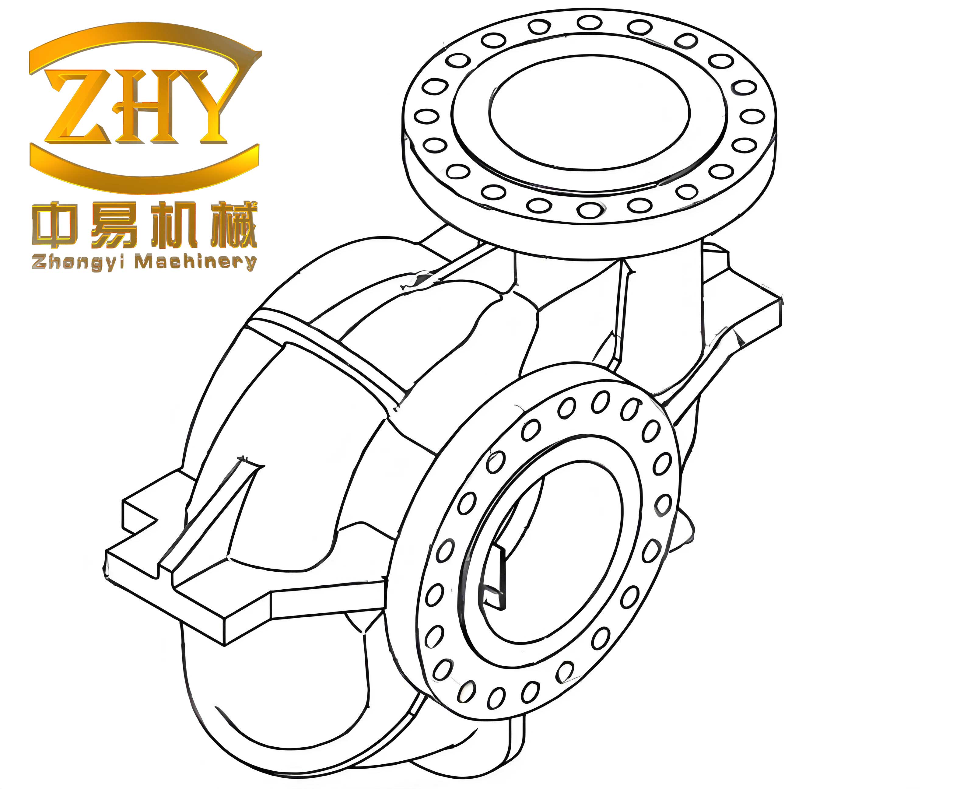
The target component is a regulator housing, a classic example of a critical shell casting. Its specifications dictate the rigor of the process design.
| Parameter | Requirement/Specification |
|---|---|
| Working Pressure | 31.4 MPa (320 kgf/cm²) |
| Leak Test | Entire internal cavity & flow channels tested at 47.1 MPa; zero leakage allowed. |
| Machining & Finish | End faces ground; internal bore honed. Surface roughness Ra ≤ 0.8 µm. |
| Dimensional Tolerance | Critical casting dimensions for flow channels: ±0.5 mm. |
| Wall Thickness | Max: 28 mm, Min: 12 mm (highlighting uneven section). |
| Material | Ductile Iron (QT450-10 or equivalent). |
| Casting Weight | Approximately 4.5 kg. |
Process Design Principles and Comparative Analysis
The transition from traditional to equilibrium-based design requires a clear understanding of the differences. The following table contrasts the two approaches for shell castings.
| Aspect | Traditional Sequential Solidification | Equilibrium Solidification & Limited Feeding |
|---|---|---|
| Guiding Principle | Maintain open feeding path from casting to riser until complete solidification. | Provide external feed only until the Equilibrium Point (t_E), then choke the feed path. |
| Riser Role | Major liquid reservoir; must solidify last. | Limited liquid reservoir to cover shrinkage deficit before t_E; designed to solidify at or before the casting’s critical section. |
| Handling of Graphite Expansion | Expansion can cause back-flow into riser, leading to internal shrinkage in the casting. | Expansion is contained within the casting after feed path is choked, enabling self-feeding and densification. |
| Riser Size | Generally larger, based on modulus calculations ensuring later solidification. | Generally smaller, based on calculations for required feed volume up to t_E. |
| Process Yield | Lower, due to larger risers and gating. | Higher, due to optimized, smaller feeding systems. |
| Suitability for Shell Castings | Prone to leakage defects in pressure-critical areas. | Highly effective for achieving pressure-tight integrity. |
The mathematical basis for the limited feeding requirement is crucial. The total feeding demand (V_feed) of a ductile iron casting up to the Equilibrium Point can be expressed as:
$$ V_{feed} = V_{casting} \cdot (\alpha_{liquid} + \alpha_{eutectic} – \eta_{graphite}(t_E)) $$
Where:
V_casting is the casting volume,
α_liquid is the liquid contraction coefficient,
α_eutectic is the contraction during austenite shell formation, and
η_graphite(t_E) is the fraction of graphite expansion realized by time t_E.
The riser must be designed to supply this V_feed, not the full solidification shrinkage.
Step-by-Step Process Design for Shell Castings
1. Pouring Position and Parting Line
For shell castings requiring high surface quality on large flat faces, the primary flat surface should be oriented downwards in the mold. This minimizes defects like sand inclusions and gas holes on critical surfaces. To facilitate gating system placement, core setting, and pattern withdrawal, a horizontal parting line is typically chosen. This is a standard but vital first step for any shell casting design.
2. Mold and Core Materials
The choice of materials directly impacts surface finish and dimensional accuracy of the final shell castings.
- Mold: Clay-bonded, oven-dried sand (green sand is less suitable for high-pressure castings due to higher gas content). A carbonaceous (graphite-based) water-wash coating is applied to improve surface finish and prevent metal penetration.
- Cores: For complex internal cavities typical of shell castings, cold-box or warm-box resin-bonded sands (e.g., phenolic urethane) are preferred for their high strength, good collapsibility, and excellent dimensional stability. Cores are coated with a refractory base layer (e.g., alumina) followed by a graphite top coat, and dried using residual heat to eliminate moisture and prevent gas defects.
3. Gating and Feeding System Design Based on Equilibrium Theory
This is the most critical phase where the theory is applied. The goal is to create a system that feeds efficiently before t_E and then becomes isolated. A “riser-gate” or “gate-riser” combination is highly effective for shell castings.
Concept: Instead of a separate riser, the gating system itself is designed to act as the feeder. Metal is introduced from the top of the casting (creating a favorable temperature gradient), and the main runner or a specially designed chamber around the sprue acts as the feeding reservoir. The ingate(s) function as the feeding neck. This neck must be designed to solidify at the desired time to choke the feed.
Design Calculations:
- Total Metal Weight: Estimate total poured weight (
W_total), including casting, gating, and feeding channels. For an initial yield estimate of 65%,W_total = W_casting / 0.65 ≈ 4.5 kg / 0.65 ≈ 6.9 kg. - Ingate (Feeding Neck) Total Area: Use empirical formulas or flow rate calculations. Based on hydraulic principles and typical pour times for shell castings of this weight (3-6 seconds), the ingate area (
ΣA_ingate) can be sized. A common relation is derived from the Bernoulli equation:
$$ \Sigma A_{ingate} = \frac{W_{total}}{ \rho \cdot \mu \cdot t_p \cdot \sqrt{2gH_p} } $$
Where:
ρis the density of liquid iron (≈7000 kg/m³),
μis the discharge coefficient (≈0.6 for partially choked systems),
t_pis the planned pouring time (e.g., 4 s),
gis gravity (9.81 m/s²),
H_pis the average effective metal head during pouring (m).
For our example, withH_p ≈ 0.15m, calculation yieldsΣA_ingate ≈ 2.0 cm². - Number and Shape of Ingates: To avoid excessive heat concentration at a single neck—which can delay its solidification and cause shrinkage in the shell casting at the junction—multiple smaller ingates are used. For instance, four ingates, each with an area of
0.5 cm². The neck should be designed with a “choke” shape—wider at the runner end and narrower at the casting connection—to promote earlier solidification at the casting junction.
$$ A_{single\_ingate} = \frac{\Sigma A_{ingate}}{N} $$ - Runner (Feeding Reservoir): The horizontal runner or a specially designed ring-shaped runner acts as the riser. Its cross-sectional area must be larger than the total ingate area to ensure it remains liquid longer, following the rule:
$$ A_{runner} \geq 1.2 \times \Sigma A_{ingate} $$
A trapezoidal section runner with an area of approximately2.5 cm²is suitable. - Sprue: The sprue base area should be larger than the runner area to prevent aspiration. A common ratio is:
$$ A_{sprue\_base} \approx 1.1 \times A_{runner} $$
A circular sprue with a bottom diameter yielding an area of2.8 cm²is selected.
The following table summarizes the designed system parameters for this shell casting:
| System Element | Design Parameter | Calculated Value |
|---|---|---|
Total Poured Weight (W_total) |
Estimated | ~6.9 kg |
Ingate Total Area (ΣA_ingate) |
Flow equation | 2.0 cm² |
Number of Ingates (N) |
Thermal distribution | 4 |
| Single Ingate Area | A_single = ΣA_ingate / N |
0.5 cm² |
Runner Area (A_runner) |
A_runner ≥ 1.2 * ΣA_ingate |
2.5 cm² (trapezoid) |
Sprue Base Area (A_sprue) |
A_sprue ≈ 1.1 * A_runner |
2.8 cm² (ø19mm) |
4. Key Process Calculations and Control Parameters
Once the system is sized, critical operating parameters are verified to ensure they align with the goals for producing sound shell castings.
Pouring Time (t_p): Verified using the actual ingate area.
$$ t_p = \frac{W_{total}}{\rho \cdot \Sigma A_{ingate} \cdot \mu \cdot \sqrt{2gH_p}} $$
Plugging in the numbers confirms a pour time of about 4 seconds, which is appropriate.
Metal Rise Speed in the Mold Cavity: Critical for thin-walled sections of shell castings to prevent mist runs. It is calculated by dividing the casting height by the pouring time.
$$ v_{rise} = \frac{H_{casting}}{t_p} $$
For a casting height of 0.12m, v_rise ≈ 0.03 m/s, which is acceptable for medium-section castings.
Feed Path Solidification Control: The most critical calculation. The modulus (Volume/Area) of the ingate neck (M_ingate) must be less than the modulus of the casting section it feeds (M_casting) and greater than the modulus of the runner/riser (M_runner) to ensure the desired solidification sequence: Runner solidifies last, then ingate, then casting. This ensures the feed path is choked at the ingate.
$$ M_{runner} > M_{ingate} < M_{casting\_section} $$
This inequality is checked using geometric modulus calculations for each element.
Solidification Simulation and Process Control
While calculations provide a baseline, modern practice for critical shell castings employs numerical solidification simulation to visualize the temperature fields and predict shrinkage risks. Simulation helps in:
- Identifying the last-to-freeze zones and ensuring they are within the casting body, not isolated.
- Verifying that the thermal center of the gating/riser system remains liquid longer than the casting’s feeding zone only until the estimated
t_E. - Optimizing the ingate neck design to achieve the targeted choke time.
Furthermore, process control is paramount:
- Cooling Rate Management: For ductile iron shell castings, controlled cooling after pouring is essential to promote sufficient graphite nucleation and growth for the self-feeding expansion. Shakeout time must be optimized based on casting modulus and alloy composition.
- Chemical Composition Control: The carbon equivalent (CE), magnesium content, and inoculant type/amount are tightly controlled. A higher CE (but below the eutectic to avoid graphite flotation) promotes greater graphitization expansion. Effective inoculation ensures a fine, uniform graphite nodule distribution, which maximizes the expansion pressure for self-feeding within the shell casting.
- Pouring Temperature: An optimal pouring temperature is maintained—high enough to ensure fluidity and complete filling of thin sections, but low enough to reduce total liquid shrinkage and promote rapid establishment of a solid skin, shortening the time to
t_E.
Conclusion and Benefits
The application of Equilibrium Solidification Theory and the principle of Limited Feeding provides a robust, scientific framework for designing manufacturing processes for high-integrity, high-pressure shell castings. By consciously designing the feeding system to cease operation at the Equilibrium Point, we harness the inherent graphitization expansion of ductile iron to densify the casting from within. This methodology directly addresses the shortcomings of traditional sequential solidification for these materials.
The tangible benefits observed in the production of shell castings like regulator housings include:
- Enhanced Internal Soundness: Elimination of subsurface shrinkage porosity, leading to 100% success in high-pressure leak tests.
- Improved Process Yield: Significant reduction in riser size and gating volume increases metal yield, often from below 50% to over 65%.
- Simplified Finishing: Smaller, strategically placed feeding systems are easier to remove, reducing cleaning and grinding costs.
- Adaptive Robustness: The design is less sensitive to normal fluctuations in melting and sand properties, resulting in more consistent quality for serial production of shell castings.
In summary, transitioning to an equilibrium-based design philosophy is not merely a change in calculation rules but a fundamental shift in understanding the solidification dynamics of ductile iron. For engineers and foundries specializing in pressure-critical shell castings, mastering and applying this theory is essential for achieving reliable, cost-effective, and high-performance components.