

Figure 1 shows the structural diagram of the roller supported horizontal centrifugal casting machine including foundation and foundation. The casting mold is supported by four symmetrical rollers, each roller is supported by a pair of rolling bearings, the bearing seat is fixed on the foundation, and the foundation part is embedded in the foundation. One of the rollers is connected with the motor through the belt drive, and the roller drives the casting mold to rotate.
According to the structure of centrifugal casting machine, the vibration model is established, as shown in Figure 2. Among them, M1 and M2 are the mass of the cast rotor and foundation respectively, excluding the mass of the roller and the bearing seat, as well as the stiffness and damping of the bearing seat. Considering the vibration of the rotor and foundation in the vertical direction and the tilt movement of the foundation around the horizontal axis, X1 and X2 are the vertical displacement of the rotor and foundation respectively, and θ 2 is the tilt movement angle of the foundation. KC is the contact stiffness between the roller and the mold, KB and CB are the radial stiffness and damping of the rolling bearing respectively, KF, K θ F and CF are the stiffness coefficient of the foundation in the vertical direction, the rotational stiffness coefficient around the horizontal axis and the damping coefficient in the vertical direction respectively. The calculation method of KC, KB and CB is shown in the content. The direction is the normal direction of contact between roller and mold, which can be equivalent to horizontal direction and vertical direction.
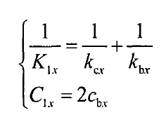
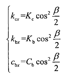
Where, β is the roller support angle, and the subscript x represents the vertical direction (x direction), then the equivalent stiffness and damping of roller support in the vertical direction are:
