
As a foundry engineer specializing in heavy equipment components, I’ve developed specialized techniques for producing critical . This comprehensive guide details the methodology for manufacturing counterweights for Liebherr excavators, focusing on the unique challenges presented by these massive components.
Component Characteristics and Material Specifications
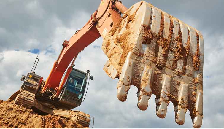
The counterweight represents a critical excavator casting part with distinctive features impacting production strategy. Its bread-like geometry combines multiple curved surfaces with critical mounting planes requiring precise dimensional tolerances. Manufactured in HT100 gray iron, this 6-ton component presents extreme section thickness variations ranging from 30mm to 455mm. The material composition follows standard gray iron specifications:
| Element | Composition (%) | Role in Casting |
|---|---|---|
| Carbon | 3.0-3.4 | Graphite formation |
| Silicon | 1.9-2.3 | Graphitization promoter |
| Manganese | 0.5-0.8 | Sulfide control |
| Phosphorus | <0.15 | Fluidity enhancement |
| Sulfur | <0.12 | Inhibition parameter |
The graphite expansion coefficient ($\alpha_g$) fundamentally impacts shrinkage compensation according to:
$$ \Delta V = V_0 \cdot \alpha_g \cdot \Delta T $$
Where $V_0$ represents initial volume and $\Delta T$ is the temperature differential during solidification. This relationship becomes critical when designing feeding systems for such massive excavator casting parts.
Pattern Design and Molding Strategy
Our split-pattern approach addresses the component’s geometric complexity while ensuring dimensional accuracy. The bisection plane follows the component’s natural parting line, with precision alignment maintained through dowel pins and bolted connections. The molding sequence implements an inverted position strategy:
- Position curved surfaces downward in drag section
- Mount pattern on molding platform with lifting screws
- Compact high-strength molding sand (90 hardness minimum)
- Execute 180° mold flip before cope assembly
The sand mixture formulation proves critical for surface finish quality:
| Material | Percentage | Function |
|---|---|---|
| Silica Sand (AFS 60) | 85% | Base aggregate |
| Bentonite Clay | 10% | Binder |
| Cellulose Additives | 3% | Collapsibility |
| Coal Dust | 2% | Surface finish |
Gating and Feeding System Engineering
The dual-pour methodology addresses molten metal volume requirements exceeding single furnace capacity. Two 3.5-ton ladles deliver iron through a stepped gating configuration with calculated parameters:
$$ Q = A \cdot v \cdot t $$
Where $Q$ = metal flow rate (kg/s), $A$ = choke area (cm²), $v$ = flow velocity (m/s), and $t$ = pouring time (s). Our optimized gating ratios (1:2:1.5 for sprue:runner:ingate) ensure laminar flow for this critical excavator casting part. Each ingate measures 25×50mm with strategic placement relative to thick sections.
The feeding system employs six strategically positioned risers, including four knuckle-type feeders at critical mass concentration points. The feeding efficiency ($E_f$) follows Chvorinov’s relationship:
$$ E_f = \frac{V_r / V_c}{ (T_s)_r / (T_s)_c } \times 100\% $$
Where $V$ represents volume, $T_s$ is solidification time, with subscripts $r$ for riser and $c$ for casting. Our 20×300mm contact surfaces maximize thermal transfer between the casting and feeders.
Specialized Process Implementation
Embedded thread inserts require precision placement through removable core prints. The installation follows the mechanical relationship:
$$ F_f = \mu \cdot F_n $$
Where $F_f$ = frictional resistance during placement, $\mu$ = friction coefficient, and $F_n$ = normal force from fastening torque. This ensures positional accuracy within ±1.5mm tolerance for this essential excavator casting part.
Thermal management protocols include:
- Preheating ladles to 800°C minimum
- Controlled pouring temperature: 1280-1320°C
- Cooling rate limitation: <30°C/hour during critical phase
Quality Assurance and Process Control
Preventing defects in such massive excavator casting parts requires comprehensive parameter control. Critical measures include:
| Parameter | Control Range | Measurement Method |
|---|---|---|
| Sand Hardness | 88-92 | Brinell-type tester |
| Mold Drying | 24h @ 250°C | Thermocouple monitoring |
| Shakeout Time | >24 hours | Thermal modeling |
| Cooling Gradient | <5°C/cm | IR thermography |
Graphite expansion management follows the modified Hooke’s law relationship for constrained expansion:
$$ \sigma = E \cdot \alpha_g \cdot \Delta T \cdot (1 – \nu) $$
Where $\sigma$ = induced stress, $E$ = Young’s modulus, $\alpha_g$ = graphite expansion coefficient, $\Delta T$ = temperature difference, and $\nu$ = Poisson’s ratio.
Conclusion
Successfully manufacturing these massive excavator casting parts requires integrated control of pattern engineering, material science, thermal dynamics, and process precision. The methodologies developed ensure dimensional stability, surface quality, and structural integrity despite extreme section variations. These principles apply broadly to heavy equipment components where mass distribution and aesthetic requirements coexist with functional demands. Continuous refinement of these techniques pushes the boundaries of what’s achievable in industrial-scale casting operations for critical machinery components.