
The mechanical properties and machinability of gray cast iron samples for engine cylinder block were tested, and the microstructure of the matrix was observed.
1. Determination of mechanical properties of gray cast iron for engine cylinder block
The tensile strength test of gray cast iron for engine cylinder block is carried out on the WAW-Y500 universal material testing machine of the Institute of engineering and materials of YITUO Group. The average value of four tensile samples is taken for the tensile strength; Carry out Brinell hardness measurement on the sample with hb-3000 Brinell hardness tester. The load is 750 kg and the indenter is Φ 5 mm。 Measure the hardness of the step sample, and compare the section sensitivity of the sample through the hardness of different thickness parts of the step sample; Use mh-3 microhardness tester to measure the microhardness of pearlite matrix in metallographic structure. Load 200 g and maintain the load for 10 s. measure ten points on each sample, and then calculate the average value to obtain the microhardness.
2. Determination of cutting performance of gray cast iron for engine cylinder block
There are many indicators to measure the machinability of gray cast iron for engine cylinder block, which can be studied by parameters such as cutting force, cutting heat and tool wear. In order to evaluate the machining performance of materials, researchers generally study through parameters such as cutting force, cutting heat and tool wear. The cutting force measuring device and process are simple and direct, which can dynamically study the changes of cutting performance in the cutting process of gray cast iron for engine cylinder block; Tool wear is the most direct way to evaluate the cutting performance of materials, especially when various factors are stable, but the experimental material consumption is large and the experimental cycle is long. In this experiment, the research on the cutting performance of gray cast iron for engine cylinder block adopts the evaluation method based on the cutting force and the combination of cutting force and tool wear.
The cutting force of gray cast iron for engine block is measured by stress-strain measurement system. The stress-strain measuring system consists of qb-07 double parallel octagonal ring dynamometer, bridge circuit and dh5923 dynamic and static strain measuring instrument. The stress-strain measurement system is suitable for ordinary lathe, and its measurement data is accurate and intuitive. Qb-07 double parallel octagonal ring dynamometer is an elastic element that can convert the change of cutting force into the change of electric quantity. Its structural shape is shown in Figure 1. The octagonal ring part in the middle is an elastic element, which is divided into upper ring and lower ring. The front end is provided with square holes for installing turning tools, and the rear round holes are used for installing and fastening on the lathe tool holder.

When cutting gray cast iron for engine cylinder block, the deformation and friction produced by the tool cause the cutting force. For the tool, the cutting force comes from two aspects: one is the resistance caused by the elastic and plastic deformation of the workpiece material in the three deformation areas; The second is the resistance caused by the friction between workpiece, chip and tool. The total resultant force F of the cutting force acting on the tool is called the cutting force. F is often decomposed into the following three components in turning, as shown in Figure 2. Main cutting force FZ – is the component force along the cutting speed direction, also known as tangential force. Feed resistance FX – is the component force of F in the feed direction, which is also called axial force in cylindrical turning. Cutting resistance FY – is the component force of F in the cutting direction. In cylindrical turning, it is also called radial force. Qb-07 double parallel octagonal ring dynamometer can measure three-dimensional forces FX, FY and FZ at the same time.

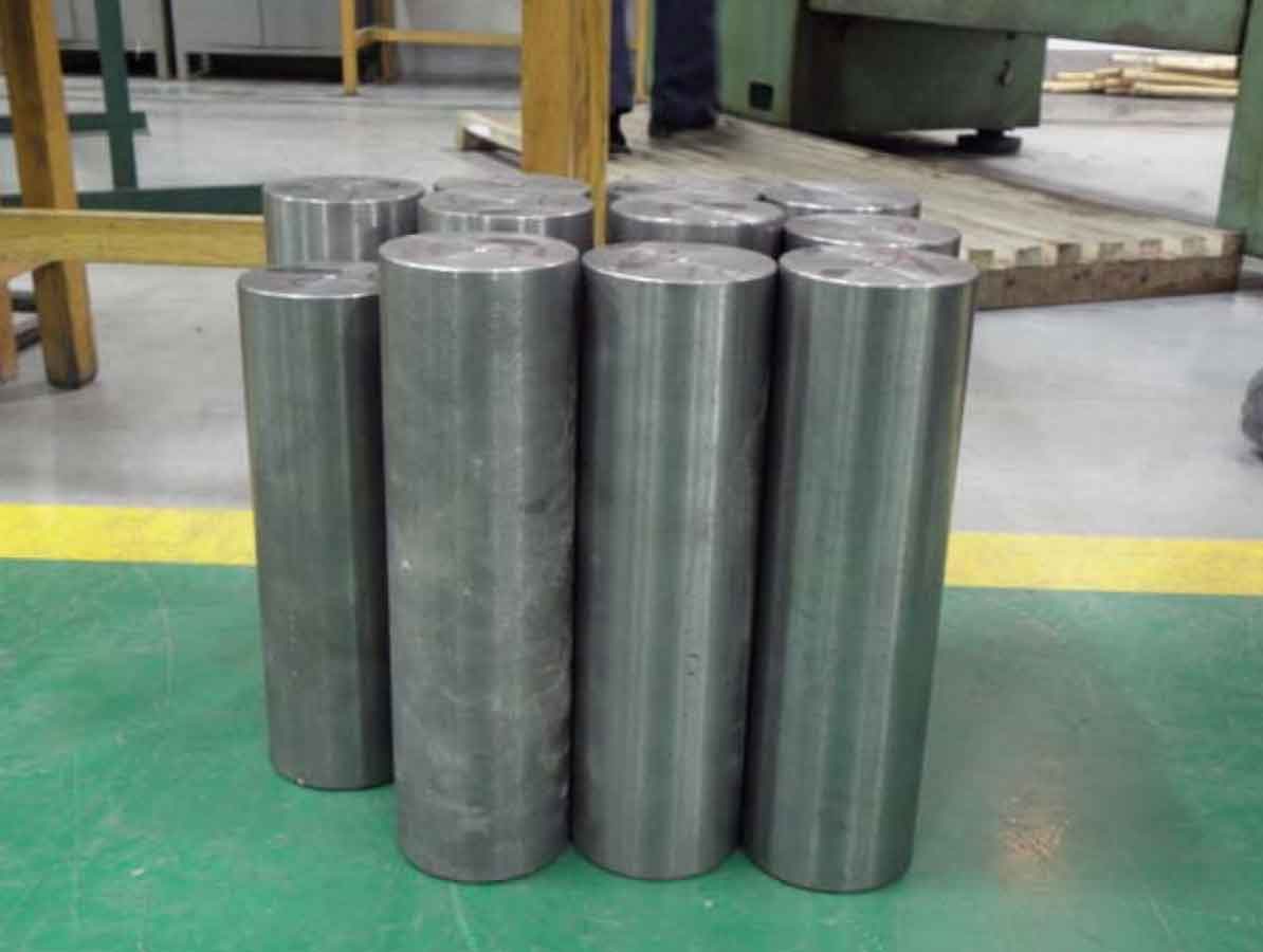
The cutting force of gray cast iron for engine block is measured on CA6140 lathe, and the cutting workpiece is shown in Figure 3. In order to ensure the consistency of tool angle, the machine clamp turning tool is selected. Each test blade is YG8 cemented carbide blade of the same batch of products produced by the same manufacturer. In the experiment, ewln-95 ° eccentric head side cutter and nsdn-45 ° straight cutter produced by Yiquan, Taiwan were selected as the machine clamp turning tool. The tool bar is connected with the lathe tool rest table through the octagonal ring force measuring instrument, and the resistance change of the strain gauge caused by the change of cutting force is measured by dh5923 dynamic strain measuring instrument.

The experiment adopts dry cutting, and the center is used in the cutting process of gray cast iron for engine cylinder block, so as to achieve the function of fixed support and reducing workpiece vibration. In order to ensure the coaxiality between the machined cylindrical surface and the axis of the machine tool and the same diameter of the machined surface after the workpiece is clamped, the surface of the sample is turned a little during the comparative experiment. Because the cutting length is very small when measuring the cutting force, the influence on the tool wear can be ignored. In order to avoid the influence of the change of tool reinstallation angle on the cutting force in the same group of machining experiments, the cutting force experiment of a group of machining parameters is completed with the same tool. During the experiment, the same set of processing parameters only use one clamp blade to cut four samples. During the cutting experiment, the spindle speed and feed rate of the machine tool remain unchanged, and only the cutting depth is changed in each set of experimental parameters. After cutting, the wear morphology of the tool surface was observed and analyzed by JSM-5610LV scanning electron microscope. The cutter bar and cutter are shown in Figure 4.

3. Microstructure analysis of gray cast iron for engine cylinder block
After the tensile strength of the tensile sample is tested, select the sample closest to its average value, and cut a part horizontally at the fracture to prepare the metallographic sample. Olympus pmg3 optical microscope and siscas are used V8. 0 metallographic image analysis software to study the microstructure of the sample, such as graphite morphology and content, matrix structure, pearlite distribution and content.