
According to the flaw detection results, there are many casting defects in the cast steel joints, and many casting defects appear in the key stress areas of the cast steel joints. Casting defects on cast steel joints can be divided into two categories. One is surface defects, which appear on the surface of cast steel joints and have a certain depth, such as cold and hot cracks in casting; The other is the point defects in the cast steel joints, mainly including pores and inclusions. The study of these irregular defects can usually be simplified, and the internal strip defects can also be treated as cracks. According to the relevant theories of fracture mechanics, cracks are divided into open cracks (type I cracks), sliding cracks (type II cracks) and tearing cracks (type III cracks). If there are two or more types of cracks at the same time, it is called compound crack. In the experimental research, mode I crack is the main research type. Because it is more dangerous than other cracks, if there is a composite crack in the structure, it is often treated as mode I crack for safety reasons.

In fracture mechanics, internal casting defects are often regarded as buried cracks, and cracks on the surface are regarded as surface cracks. The calculation model of deep buried crack is a sheet crack in an infinite matrix, and the calculation model of surface crack is a sheet crack exposed on a free surface in a semi infinite matrix. Since the orientation of the sheet crack in the object is usually difficult to judge from the results of ultrasonic flaw detection, the direction of the crack surface perpendicular to the tensile stress can also be taken in the calculation to ensure the safety of the calculation results. When testing cast steel joints, it is often not very accurate to determine the type of casting defects. Therefore, it is a fuzzy problem to classify the casting defects into what kind of mechanical model. It is advisable to classify some small undetermined strip defects as cracks, and evaluate these casting defects according to the method of evaluating cracks. Assuming that the cast steel joint is in service with damage, three positions a, B and C are selected for research according to the location of casting defects and stress concentration area indicated by the flaw detection results. Position a is the area near the intersection line, which is located on the main pipe, B is the stress concentration area of branch pipe, and C is the area affected by weld. For these three positions, the surface defects are established respectively, and the stress intensity factor of casting defects is calculated.

10 node tetrahedral element of solid187
According to the theory of fracture mechanics, the stress at the crack tip tends to infinity, and the crack tip has stress singularity. In order to overcome the problem that it is difficult to obtain the stress intensity factor at the crack tip in the finite element mesh, the isoparametric singular element can be used. Henshell and barsoum pointed out that the plko plane of the 20 node isoparametric element can be degenerated into a straight line without using a special crack tip singular element. By moving the node in the edge of the isoparametric element near the crack tip to 1 / 4 of the crack tip, the stress at the crack tip corner can have the singularity of 1 / root sign R. this degenerated element is usually called distorted 1 / 4 node singular element. Two typical units are shown in Figure 1.

The surface crack is constructed by using the fracture tool, several very short cylinders are connected to simulate the crack, the grid is divided around the center line, and then the stress intensity factor value of each point is obtained. The default solid186 and solid187 are selected for the mesh element type, and the three-dimensional degenerate singular isoparametric element at the crack front is generated by the degradation of solid186 element.
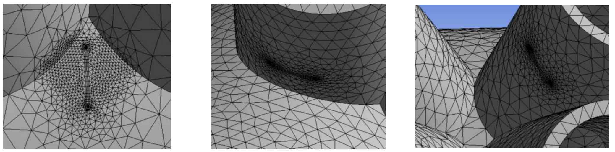
Next, the crack is located by establishing the local coordinate system in ANSYS Workbench, and the singular element is selected to mesh the crack front. At the same time, in order to reflect the rapidly changing stress and deformation field, the crack area grid is locally refined, and the finite element model of the crack is shown in Figure 3. Specific parameters of crack a: casting defect half length C = 30mm, depth a = 10mm, crack B, C and a have the same shape. The element division near the crack is shown in Figure 4:

For cracks a, B and C, keep the casting defect depth a = 10mm, and study the influence of the change of casting defect length on SIF. The calculation results are shown in Fig. 6. For this working condition, the effects of cracks at a, B and C are different. When the crack depth remains unchanged, the SIF value will increase with the increase of the initial crack length. The influence of casting defect depth on the bearing capacity of cast steel joints was studied by keeping the casting defect length 2C = 60mm unchanged. The calculation results are shown in Figure 7. When the crack length does not expand, the SIF value will increase with the increase of the initial crack length. Casting defects of the same size in different areas have different mechanical effects on cast steel. Therefore, it is inappropriate to evaluate defects of the same shape as the same grade in the acceptance specification of steel castings. This section is only a discussion on the evaluation of strip defects, because cast steel is a low-alloy medium strength steel, strip defects are not the source of fatigue cracks in the strict sense, and certain conditions are required for strip defects to develop into fatigue cracks. Even if it develops into fatigue crack, the crack tip may be passivated, but it still has some enlightening significance for the quality evaluation of cast steel joints.

Stress intensity factors corresponding to different crack depths