
As a foundry engineer with decades of experience, I have dedicated my career to advancing the production and finishing of machine tool castings. These castings form the backbone of precision manufacturing equipment, demanding exceptional dimensional stability, surface integrity, and mechanical strength. The journey from molten metal to a flawless machine tool casting is fraught with challenges, from inherent casting defects to the arduous post-processing stages. In this comprehensive account, I will share my first-hand insights into optimizing casting processes for machine tool castings and the groundbreaking development of a flexible grinding and cutting machine tool that revolutionizes their finishing. The integration of these technologies is pivotal for enhancing the quality and efficiency of machine tool castings on a global scale.
The production of high-integrity machine tool castings begins with understanding and mitigating casting defects. Common issues like shrinkage cavities, porosity, and slag inclusions can severely compromise the performance of machine tool castings. For instance, shrinkage defects often arise from inadequate feeding during solidification. The solidification time, a critical parameter, can be estimated using Chvorinov’s rule:
$$ t = B \left( \frac{V}{A} \right)^n $$
Here, \( t \) is the total solidification time, \( V \) is the volume of the casting, \( A \) is its surface area, and \( B \) and \( n \) are constants dependent on mold material and casting conditions. For machine tool castings, which often have complex geometries, a high \( V/A \) ratio can lead to longer solidification times and increased risk of shrinkage. To address this, riser design must be optimized to ensure sufficient feed metal. The efficiency of a riser can be modeled using the feeding distance equation:
$$ L_f = k \cdot \sqrt{T_s} $$
where \( L_f \) is the maximum feeding distance, \( k \) is a material constant, and \( T_s \) is the section thickness. Proper application of these principles is essential for producing sound machine tool castings.
The following table summarizes key defects, their root causes, and specific impacts on machine tool castings:
| Defect Type | Primary Causes | Impact on Machine Tool Castings |
|---|---|---|
| Shrinkage Cavity and Porosity | Inadequate riser size or placement, improper cooling rates, low feed metal pressure | Creates stress concentration points, reduces load-bearing capacity, and can lead to catastrophic failure under dynamic loads in machine tools. |
| Slag and Inclusion Defects | Turbulent metal flow in gating systems, improper skimming, reaction products from mold materials | Causes surface and subsurface flaws that impair machinability, leading to tool wear and dimensional inaccuracies during final machining of machine tool castings. |
| Gas Porosity (Pinholes, Blows) | High moisture or volatile content in sand molds, insufficient mold venting, dissolved gases in melt | Decreases effective cross-sectional area, lowering stiffness and damping capacity—critical properties for vibration resistance in machine tool castings. |
| Mold Shifts and Core Deviations | Inaccurate mold assembly, insufficient core support, mold wall movement | Results in dimensional errors and misalignments, making it difficult to achieve the tight tolerances required for assembled machine tool structures. |
Process optimization for machine tool castings involves a multifaceted approach targeting design, metallurgy, and methodology. Gating system design is paramount for controlling metal flow. The pouring time can be calculated to minimize turbulence:
$$ t_p = \frac{W}{\rho \cdot A_g \cdot v} $$
In this formula, \( t_p \) is the pouring time, \( W \) is the weight of the casting, \( \rho \) is the metal density, \( A_g \) is the choke area of the gating system, and \( v \) is the flow velocity. A well-designed system ensures laminar flow, reducing oxide formation and slag entrapment in machine tool castings. Furthermore, the modulus method is widely used for risering. The modulus \( M \) is defined as the volume-to-cooling surface area ratio:
$$ M = \frac{V}{A_c} $$
A riser must have a higher modulus than the casting section it feeds to solidify last. For complex machine tool castings, computational solidification simulation is indispensable for predicting hot spots and optimizing feeder placement.
Another critical aspect is the control of residual stresses, which affect the long-term stability of machine tool castings. The stress developed during cooling can be approximated by:
$$ \sigma = E \cdot \alpha \cdot \Delta T $$
where \( \sigma \) is thermal stress, \( E \) is Young’s modulus, \( \alpha \) is the coefficient of thermal expansion, and \( \Delta T \) is the temperature gradient. Stress-relief annealing is often employed, with the process parameters optimized based on the alloy composition of the machine tool castings.
The table below outlines major optimization measures and their direct benefits for producing superior machine tool castings:
| Optimization Measure | Technical Implementation | Benefit for Machine Tool Castings |
|---|---|---|
| Riser System Enhancement | Use of exothermic or insulating sleeves to extend feeding range; application of pressure-assisted risers. | Virtually eliminates shrinkage porosity in thick sections, ensuring homogeneous density and strength in critical stress zones of machine tool castings. |
| Advanced Gating Design | Implementation of pressurized, tapered, or step-gating systems with ceramic filters for smooth, controlled filling. | Minimizes slag and oxide inclusions, resulting in cleaner metal with improved fatigue properties—essential for moving parts in machine tools. |
| Mold and Core Material Innovation | Use of high-permeability, low-expansion sands (e.g., chromite) and inorganic binders to reduce gas generation. | Significantly lowers gas defect rates, enhancing the pressure tightness and surface finish of machine tool castings prior to any finishing operation. |
| Controlled Solidification Technology | Strategic placement of chills and cooling fins to direct solidification sequence and promote directional solidification. | Refines grain structure, improves mechanical properties, and reduces distortion, leading to more dimensionally stable machine tool castings. |
| Alloy Modification and Inoculation | Precise addition of inoculants (e.g., ferrosilicon) and grain refiners to control graphite morphology in iron castings. | Enhances tensile strength, ductility, and machinability, which are vital for the complex machining operations that machine tool castings later undergo. |
Even with an optimized casting process, machine tool castings emerge from molds with excess material like gates, risers, and flash, and require extensive surface finishing to meet precise specifications. Traditionally, this post-casting processing has been a bottleneck, relying heavily on manual labor—a practice plagued by inconsistency, high costs, and harsh working environments. The quest for automation led to the development of specialized machines, but their rigidity often failed to accommodate the inherent dimensional variations found in sand-cast machine tool castings. This gap necessitated a paradigm shift towards intelligent, flexible systems.
The core challenge in automating the finishing of machine tool castings lies in their geometric complexity and the permissible dimensional tolerances. A cast component might have design tolerances of ±0.5 mm, but the as-cast shape can deviate by several millimeters due to shrinkage and mold wall movement. A rigid, pre-programmed tool path would either miss material or crash into the part. Therefore, a system capable of real-time adaptation is paramount. This is where the flexible grinding and cutting machine tool, a project I was deeply involved in, makes its mark. It represents a convergence of precision mechanics, advanced sensor technology, and adaptive control algorithms specifically engineered for the demands of machine tool castings.
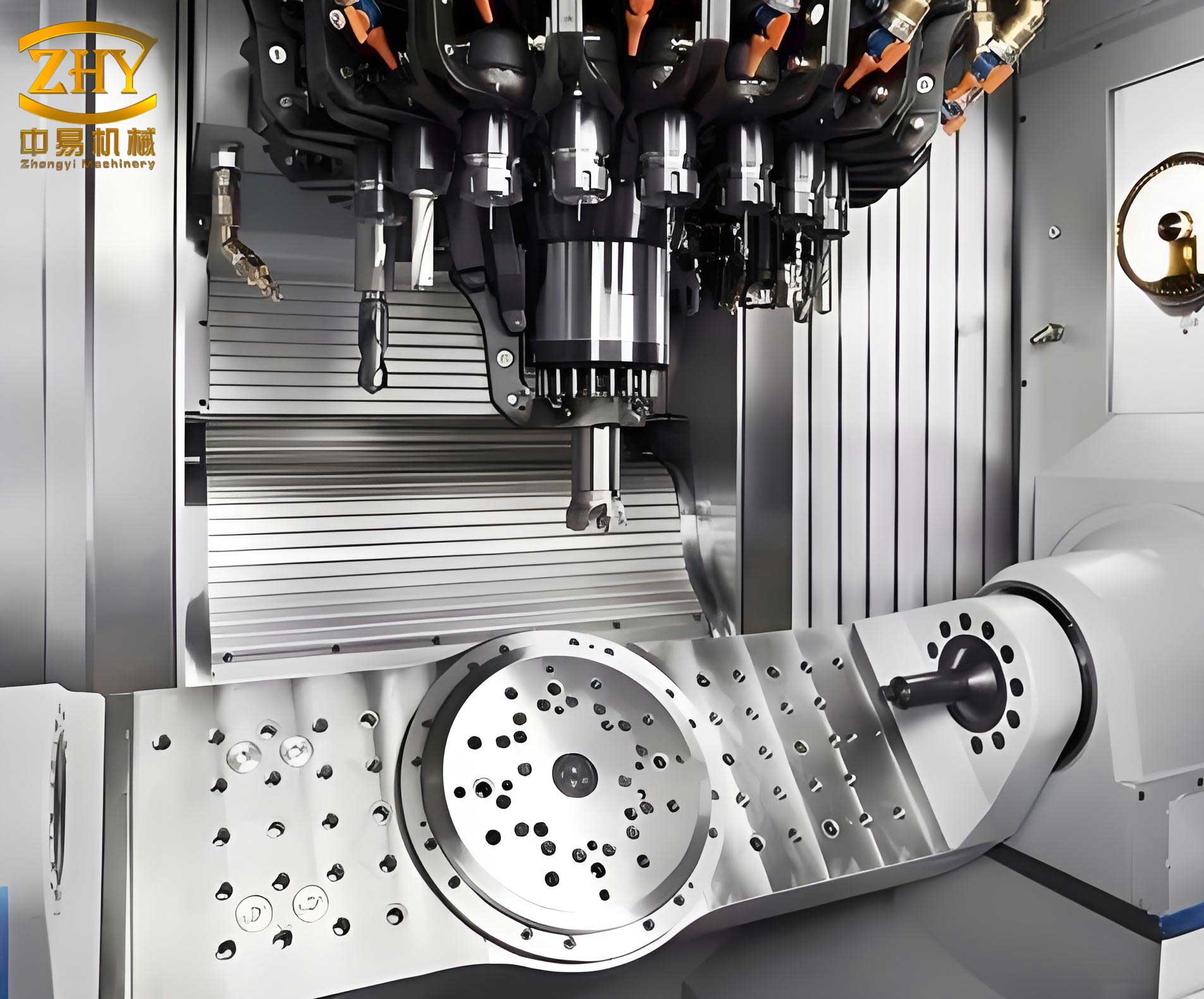
The machine’s first major innovation is its multi-sensor laser measurement system that performs real-time, on-the-fly scanning of the workpiece. Before processing, a quick scan captures the as-cast geometry. The system then compares this point cloud data to the nominal CAD model. The deviation \( \Delta \mathbf{P} \) at any point is calculated as:
$$ \Delta \mathbf{P} = \mathbf{P}_{\text{measured}} – \mathbf{P}_{\text{nominal}} $$
This deviation field is used to dynamically offset the tool path. If \( \mathbf{T}(s) \) represents the original programmed tool path as a function of path parameter \( s \), the compensated path \( \mathbf{T}'(s) \) becomes:
$$ \mathbf{T}'(s) = \mathbf{T}(s) + \mathbf{N}(s) \cdot d(s) $$
Here, \( \mathbf{N}(s) \) is the surface normal vector at \( \mathbf{T}(s) \), and \( d(s) \) is the scalar deviation measured along that normal. This real-time path compensation is the key to handling the variable geometries of machine tool castings without manual intervention.
The second breakthrough is the machine’s versatile tooling system. It can automatically interchange between a wide array of tools—resin-bonded grinding wheels for general cleaning, diamond abrasive wheels for high-hardness alloys, carbide milling cutters for precise edge finishing, and even plasma torches for heavy riser removal. This multifunctionality consolidates multiple post-processing steps into a single setup, drastically reducing handling time for large, heavy machine tool castings. The selection of tool and operating parameters (spindle speed \( N \), feed rate \( f \), depth of cut \( a_p \)) is optimized based on material removal rate (MRR) equations and desired surface finish. For grinding, the MRR can be expressed as:
$$ \text{MRR} = a_p \cdot f \cdot v_w $$
where \( v_w \) is the work speed. For milling operations on cast surfaces, the power required \( P_c \) can be estimated by:
$$ P_c = \frac{K_c \cdot \text{MRR}}{\eta} $$
with \( K_c \) being the specific cutting energy for the casting material and \( \eta \) the machine efficiency.
The kinematic structure of the machine is its third pillar of innovation. Featuring a six-axis, five-linkage configuration with an integrated tilting-rotating worktable, it provides exceptional dexterity. This allows the tool to maintain an optimal orientation relative to complex, contoured surfaces commonly found on machine tool castings, such as internal ribs, bosses, and curved ways. The forward kinematics of such a serial manipulator can be described using the Denavit-Hartenberg convention, where the position and orientation of the end-effector (tool) is determined by a homogeneous transformation matrix:
$$ T_n^0 = A_1^0 \cdot A_2^1 \cdots A_n^{n-1} $$
Each \( A_i^{i-1} \) matrix is a function of its joint variable (angle or displacement). This high degree of freedom is essential for achieving uniform material removal and fine surface finishes on all faces of a machine tool casting.
The following table details the core technological innovations of the flexible machining center and their specific value proposition for finishing machine tool castings:
| Innovation Component | Technical Description | Advantage for Machine Tool Castings |
|---|---|---|
| Real-Time Adaptive Path Compensation | Integration of 3D laser scanners with CNC controller for closed-loop,随形 (contour-following) tool path correction. | Accommodates the typical ±2-5 mm dimensional variations in as-cast parts, enabling fully automated finishing of machine tool castings without costly fixturing or manual teaching. |
| Multi-Tool Automatic Changing System | Robotic arm or carousel-based system capable of handling grinding wheels, cutting discs, milling tools, and brushes. | Enables complete processing—from rough deburring and riser removal to fine blending and edge preparation—in one clamping, minimizing cycle time and handling damage for precision machine tool castings. |
| High-Rigidity Mechanical Structure | Optimized finite element analysis (FEA)-driven design using high-grade cast iron and steel for bed, columns, and spindle housing. | Provides the static and dynamic stiffness necessary for aggressive cutting on hard cast materials, ensuring geometric accuracy and surface finish integrity of finished machine tool castings. |
| Six-Axis Five-Linkage Kinematics | Serial robotic arm or gantry-style mechanism with five simultaneously controlled axes plus a spindle tilt/rotate axis. | Allows access to undercuts and complex internal geometries, ensuring no “shadow” areas are left unfinished on intricate machine tool castings like housings and bases. |
| Intelligent Process Monitoring | Use of force, vibration, and acoustic emission sensors to monitor tool wear and process stability, adapting feeds and speeds accordingly. | Prevents tool breakage and ensures consistent finish quality across batches of machine tool castings, reducing scrap and tooling costs. |
The deployment of this flexible technology has yielded transformative results across industries reliant on high-quality machine tool castings. In automotive component manufacturing, for example, the finishing of cast iron engine blocks and transmission cases—critical machine tool castings—has seen cycle time reductions of over 40% compared to manual methods, with surface consistency improvements exceeding 30%. For the renewable energy sector, the precise finishing of large, complex wind turbine gearbox housings (another class of demanding machine tool castings) is now feasible with minimal human intervention. The economic impact is quantifiable through metrics like Return on Investment (ROI) and Overall Equipment Effectiveness (OEE). The ROI for adopting such a system can be calculated as:
$$ \text{ROI} = \frac{\text{Net Annual Savings} – \text{Annualized Machine Cost}}{\text{Annualized Machine Cost}} \times 100\% $$
Net annual savings arise from labor reduction, increased throughput, lower scrap rates, and improved quality. A typical OEE calculation, considering availability, performance, and quality rates, often shows an increase from around 60% for manual cells to over 85% for the automated flexible cell when processing machine tool castings.
The table below illustrates a simplified breakdown of benefits observed from implementing the flexible machining system for finishing various types of machine tool castings:
| Performance Metric | Manual Finishing (Baseline) | Flexible Machine Tool Finishing | Improvement |
|---|---|---|---|
| Average Finishing Time per Casting | 120 minutes | 45 minutes | 62.5% reduction |
| Dimensional Consistency (CpK index) | 1.0 – 1.2 | 1.6 – 1.8 | > 50% increase in process capability |
| Direct Labor Cost per Casting | High (2-3 operators) | Low (0.5 operator for supervision) | ~75-85% reduction |
| Rejection/Repair Rate due to Finishing Errors | 5-8% | < 1% | Over 80% reduction in scrap |
| Ability to Handle Casting Geometry Variation | High (skilled worker adaptation) | Very High (automated system adaptation) | Eliminates dependency on operator skill for machine tool castings |
The future trajectory for the production of machine tool castings is inextricably linked to further digitalization and flexibility. The next generation of systems will likely integrate the foundry’s digital thread, where the as-designed CAD model, simulation-predicted shrinkage and distortion, and real-time scan data from the casting are fused to generate an optimal first-time-right finishing path. Artificial intelligence algorithms will predict tool wear and prescribe preventive maintenance, maximizing uptime. Furthermore, the principles developed for these flexible machines are being adapted for additive manufacturing hybrid processes, where near-net-shape printed machine tool castings are finished to tight tolerances in a single setup.
In conclusion, the journey towards perfect machine tool castings is a continuous cycle of refinement in both the casting and finishing domains. Process optimization in the foundry, guided by solidification science and robust engineering principles, lays the foundation by producing sound, near-net-shape castings. The advent of intelligent, flexible grinding and cutting machine tools then completes the cycle by providing a consistent, efficient, and high-precision finishing solution capable of handling the real-world variability of cast components. This synergistic advancement is not merely an incremental improvement but a necessary evolution to meet the escalating demands for precision, productivity, and sustainability in global manufacturing. The relentless focus on enhancing every stage of production for machine tool castings will continue to drive innovation, ensuring that the machinery building our world is itself built on a foundation of unparalleled quality and reliability.