
I have developed a complete casting process for a large, heavy-section ductile iron template used in a high oil pressure injection molding machine. The component is a critical part of the clamping hydraulic system. It must withstand 20 MPa oil pressure without leakage, and it must satisfy strict ultrasonic testing, magnetic particle testing, and mechanical property requirements. The casting is a ductile iron casting with a maximum wall thickness of 365 mm and a pouring weight of 9150 kg. In this work, I addressed the process difficulties, designed the parting scheme, gating and feeding systems, and cooling system, and used CAE simulation to predict shrinkage cavity and porosity defects. I also applied micro-alloying and strict control of spheroidization, inoculation, and pouring. The final ductile iron casting met the EN 12680-3:2011 level 1 ultrasonic requirement, passed the 20 MPa oil pressure test, and achieved the specified mechanical properties and microstructure. The frequent use of the term ductile iron casting throughout this article reflects the central role of this material in the development.
1. Introduction
The locking hydraulic system of an injection molding machine has a complex structure. The hydraulic cylinder castings must operate under demanding conditions. They need high mechanical properties, and they must be free from cracks, cold shuts, shrinkage cavities, porosity, and slag inclusions. Furthermore, the castings must not leak oil under high pressure. Because of the difficulty of casting hydraulic components, many manufacturers have traditionally used forged steel. However, ductile iron casting offers a cost-effective alternative if the process is properly designed. I focused on a template for a high oil pressure injection molding machine. The product is a large, heavy-section ductile iron casting with a blank weight of 8250 kg and a pouring weight of 9150 kg. The material is QT450-10A, which is a ferritic ductile iron. The overall dimensions are 2022 mm × 1660 mm × 1020 mm, and the maximum wall thickness is 365 mm. The casting must satisfy a 20 MPa oil pressure requirement. This is a challenging task for ductile iron casting because heavy sections tend to develop graphite degeneration, shrinkage porosity, and coarse microstructure.
I identified several specific process difficulties. First, the product has eight cast holes that are directly used as oil cylinder holes. These holes must not contain shrinkage cavities or porosity, and they must not leak oil. After machining, the inner surface roughness must be Ra 0.4–0.8 µm. Second, the 365 mm thick section contains two layers of Φ30 mm oil passage holes. These through holes are connected to the oil cylinder holes and serve as high-pressure oil passages. They also must be free from shrinkage defects and must not leak. These requirements make the ductile iron casting process very demanding. I therefore adopted a systematic approach that combined theoretical calculations, CAE simulation, and careful melt treatment.
2. Component and Material Specifications
I began by defining the geometry and the technical requirements. Table 1 summarizes the main parameters of the ductile iron casting.
| Parameter | Value | Unit |
|---|---|---|
| Overall dimensions | 2022 × 1660 × 1020 | mm |
| Maximum wall thickness | 365 | mm |
| Blank weight | 8250 | kg |
| Pouring weight | 9150 | kg |
| Material designation | QT450-10A | – |
| Number of oil cylinder holes | 8 | – |
| Oil passage holes | 2 layers of Φ30 | mm |
| Required oil pressure | 20 | MPa |
Table 2 lists the technical requirements that the ductile iron casting must meet. These requirements guided all subsequent design decisions.
| Requirement | Specification |
|---|---|
| Ultrasonic testing | EN 12680-3:2011 level 1 |
| Magnetic particle testing | EN 13697:2023 level 2 |
| Surface roughness of cylinder holes | Ra 0.4–0.8 µm |
| Tensile strength | ≥390 MPa |
| Yield strength | ≥260 MPa |
| Elongation | ≥8% |
| Nodularity | ≥90% |
| Graphite size | 5–8 grade |
| Leakage at 20 MPa | None |
The combination of a heavy section and internal oil passages makes this ductile iron casting particularly difficult. The solidification time is long, which promotes graphite flotation, nodule degeneration, and shrinkage porosity. The oil passages are located in the thickest part of the casting, so they are especially vulnerable. Therefore, I had to design a process that promotes directional solidification and simultaneous solidification in critical regions.
3. Theoretical Background and Design Calculations
Before designing the gating and feeding systems, I performed several calculations. The carbon equivalent is a key parameter for ductile iron casting. I used the following equation:
$$CE = \%C + \frac{\%Si}{3} + \frac{\%P}{3}$$
For the final iron composition, this gives:
$$CE = 3.42 + \frac{2.77}{3} + \frac{0.021}{3} = 3.42 + 0.923 + 0.007 = 4.35$$
The calculated value is approximately 4.34, which is close to the eutectic point. This is desirable for good castability and feeding. I also calculated the eutectic carbon content using a common approximation:
$$C_{eut} = 4.3 – 0.3 \%Si$$
With 2.77% Si, this gives:
$$C_{eut} = 4.3 – 0.3 \times 2.77 = 4.3 – 0.831 = 3.47\%$$
The actual carbon content of 3.42% is slightly below the eutectic carbon content, which means the alloy is slightly hypoeutectic. This helps to avoid graphite flotation while still providing good feeding.
The modulus of the heavy section is an important parameter for riser design. For a large plate-like section, the modulus can be approximated by:
$$M = \frac{V}{A}$$
For the 365 mm thick section, if we consider a large slab, the modulus is approximately half the thickness:
$$M \approx \frac{t}{2} = \frac{365}{2} = 182.5 \text{ mm}$$
The solidification time can be estimated using Chvorinov’s rule:
$$t_s = B \left( \frac{V}{A} \right)^2 = B M^2$$
For ductile iron, the constant B typically ranges from 0.5 to 1.0 min/cm². Converting the modulus to centimeters gives 18.25 cm. Therefore:
$$t_s = 0.5 \times (18.25)^2 = 0.5 \times 333 = 166.5 \text{ min}$$
$$t_s = 1.0 \times (18.25)^2 = 1.0 \times 333 = 333 \text{ min}$$
So the solidification time is between 2.8 and 5.5 hours. This is a very long time, which explains why heavy-section ductile iron casting is prone to defects. To compensate, I used a combination of chills and risers. The riser modulus should be greater than the casting modulus. I used the following relationship:
$$M_r = 1.2 M_c$$
For the critical section, this would require a riser modulus of about 219 mm, which corresponds to a very large riser. Instead of using a single huge riser, I used multiple smaller risers together with extensive chilling. This approach is more practical and helps to promote simultaneous solidification in the critical oil passage regions.
The gating system was designed to ensure smooth and dispersed filling. The total pouring time can be estimated from the pouring weight and the desired filling rate. I used:
$$Q = \frac{W}{\rho t}$$
where Q is the volume flow rate, W is the pouring weight, ρ is the density of ductile iron (about 7.1 g/cm³), and t is the filling time. With a pouring weight of 9150 kg and a filling time of 119 s (from CAE simulation), the average flow rate is:
$$Q = \frac{9150 \times 1000}{7.1 \times 119} \approx \frac{9150000}{844.9} \approx 10830 \text{ cm}^3/\text{s}$$
This flow rate is distributed across eight ingates. The sprue and runner dimensions were selected to avoid turbulence. The gating ratio was:
$$A_{sprue} : A_{runner} : A_{ingate} = 1 : 2 : 2$$
This ratio helps to maintain a pressurized system and reduces the risk of air entrapment. The actual dimensions are given in Table 3.
| Element | Description | Dimension |
|---|---|---|
| Sprue | Ceramic tube | Φ100 mm |
| Runner | Trapezoidal, two | 60/70 mm (height 80 mm) |
| Ingates | Ceramic tubes, 8 | Φ40 mm |
| Filter | Placed at runner-ingate junction | – |
The riser design is summarized in Table 4. I used necked feeding risers with a diameter of 100 mm and a height of 600 mm, with a minimum height of 400 mm. Two rows of risers were placed at the highest points of the top surface.
| Parameter | Value |
|---|---|
| Riser type | Necked feeding riser |
| Riser diameter | 100 mm |
| Riser height | 600 mm |
| Minimum riser height | 400 mm |
| Number of rows | 2 |
| Position | Highest points on top surface |
The cooling system was designed with a large number of chills. The chills accelerate cooling in the hot spots and prevent shrinkage porosity. I placed chills around the oil cylinder holes and along the thick section. The chill layout was optimized using CAE simulation.
4. CAE Simulation
I used ProCAST software to simulate the filling and solidification processes. The simulation provided temperature fields, velocity fields, pressure fields, and defect predictions. The filling process was stable, and the temperature distribution was uniform. The filling time was 119 s. The solidification process took 4.5 hours. The solid fraction distribution showed that the last solidified regions were located away from the oil passage holes. The shrinkage porosity prediction indicated that no defects would form in the critical oil cylinder holes or oil passages. These results confirmed that the gating and feeding system, together with the chill layout, was reasonable.
Table 5 summarizes the key CAE simulation results.
| Parameter | Result |
|---|---|
| Filling time | 119 s |
| Solidification time | 4.5 h |
| Flow pattern | Stable and uniform |
| Temperature distribution | Uniform, no cold zones |
| Shrinkage location | Away from oil holes |
| Predicted defects | No critical defects in oil passages |
The CAE simulation also allowed me to evaluate the cooling rate. The cooling rate R is defined as:
$$R = \frac{\Delta T}{\Delta t}$$
The temperature gradient in the thick section was controlled by the chills. The heat flux q follows Fourier’s law:
$$q = -k \nabla T$$
where k is the thermal conductivity. The transient heat conduction equation is:
$$\frac{\partial T}{\partial t} = \alpha \nabla^2 T$$
where α is the thermal diffusivity. By solving these equations numerically, the software predicted the solidification sequence. I used the simulation to adjust the chill thickness and placement. The final design ensured that the oil passage regions solidified before the surrounding heavy section, which reduced the risk of porosity.
5. Melt Preparation and Treatment
The melt preparation was critical for achieving the required properties. I used a charge consisting of 40% pig iron, 40% steel scrap, and 20% returns. The carburizer addition was 1.35% of the total charge weight. The FeSi75 addition was 1.4% of the total charge weight. The base iron composition is shown in Table 6.
| Element | C | Si | Mn | P | S | Fe |
|---|---|---|---|---|---|---|
| Base iron (wt.%) | 3.60 | 1.78 | 0.25 | 0.021 | 0.019 | Bal. |
I used the sandwich method for spheroidization. The spheroidizer was a mixture of 70% light rare earth magnesium alloy and 30% yttrium-based heavy rare earth magnesium alloy. The spheroidizer addition was 1.1% of the base iron weight. The magnesium reaction lasted 105 s. The compositions of the two alloys are given in Table 7.
| Alloy | Mg | RE | Si | Ca | Ba | Al | MgO | Fe |
|---|---|---|---|---|---|---|---|---|
| Light RE Mg alloy (70%) | 5.9 | 0.49 | 44.8 | 0.98 | 2.5 | 0.49 | 0.37 | Bal. |
| Y-based heavy RE Mg alloy (30%) | 6.0 | 0.9 | 43.5 | 2.2 | – | 0.55 | 0.35 | Bal. |
The inoculant was a SiBa inoculant with an addition of 0.70% of the base iron weight. The pre-treatment agent was a high Ba treatment agent with an addition of 0.20% of the base iron weight. The compositions are shown in Table 8. I also added 0.006% pure antimony to the base iron. Antimony is a pearlite promoter, but in small amounts it refines the graphite and improves nodularity in heavy sections.
| Agent | Si | Ca | Ba | Al | S | Fe |
|---|---|---|---|---|---|---|
| SiBa inoculant | 72 | 1.0 | 2.0 | 0.70 | 0.015 | Bal. |
| High Ba pre-treatment | 62 | 0.8 | 10.5 | 0.65 | – | Bal. |
The final iron composition is shown in Table 9. The carbon equivalent was 4.34.
| Element | C | Si | Mn | P | S | Mg | RE | Sb | CE |
|---|---|---|---|---|---|---|---|---|---|
| Final iron (wt.%) | 3.42 | 2.77 | 0.25 | 0.021 | 0.0098 | 0.035 | 0.0085 | 0.0056 | 4.34 |
After the spheroidization and inoculation, I transferred the iron to the pouring station. I skimmed the slag and performed a floating silicon inoculation with 0.08% inoculant. I then poured the iron into the pouring ladle and allowed it to stand for 5 minutes. The pouring temperature was 1295°C. This relatively low pouring temperature helped to reduce shrinkage and gas defects. The pouring process was controlled to avoid turbulence and slag entrapment.
6. Results
The castings were produced according to the designed process. After cleaning and machining, the oil cylinder holes had no casting defects, and the surface roughness was within Ra 0.4–0.8 µm. The 20 MPa oil pressure test showed no leakage. The ultrasonic testing results met EN 12680-3:2011 level 1, and the magnetic particle testing results met EN 13697:2023 level 2.
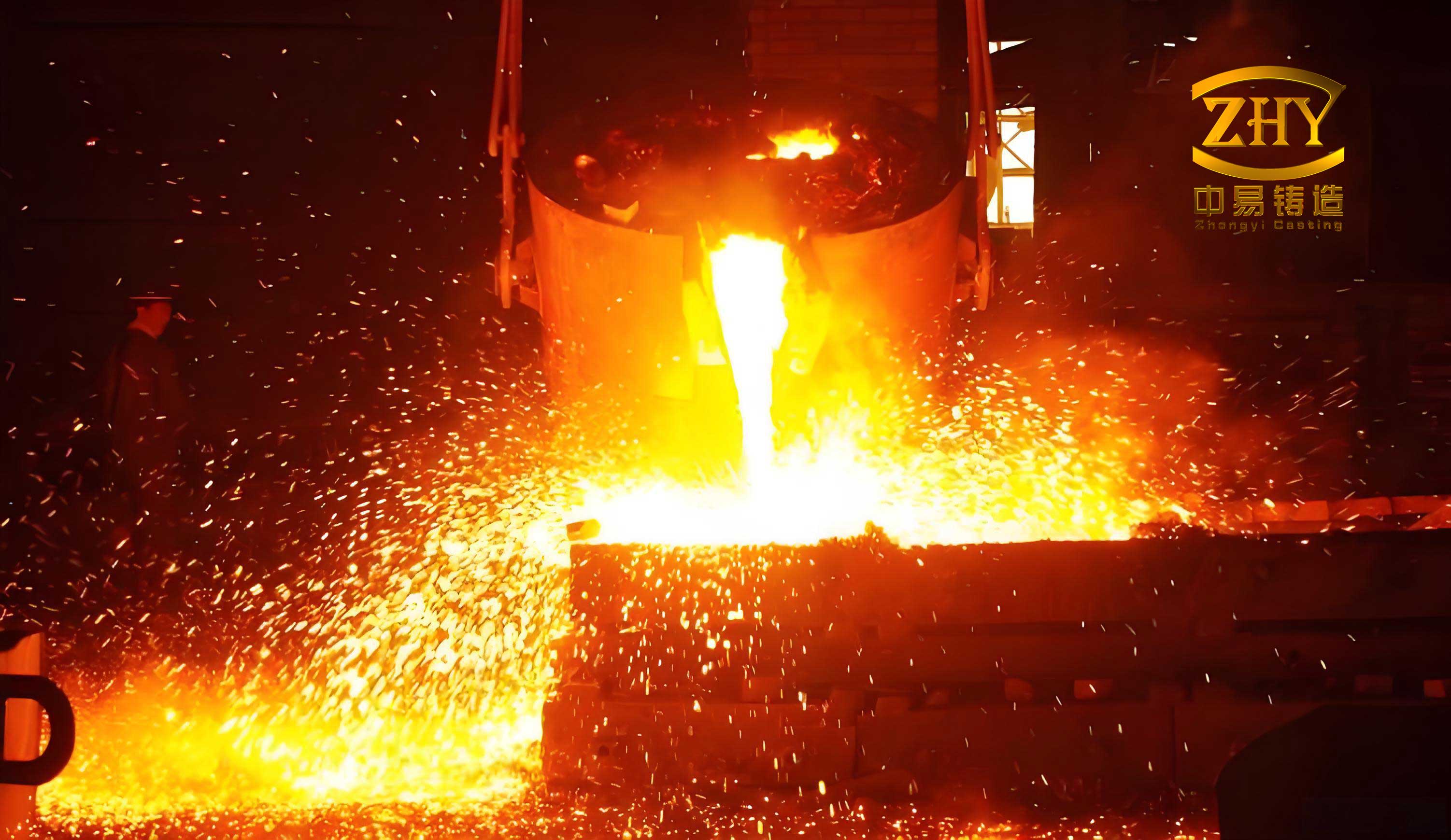
I inserted the figure of the ductile iron casting below to illustrate the final product.
The mechanical properties and microstructure were evaluated using cast-on test blocks. The test blocks were D-type according to GB/T 1348-2019, with dimensions 70 mm × 105 mm × 200 mm. Table 10 compares the measured properties with the customer requirements.
| Property | Customer requirement | Measured |
|---|---|---|
| Tensile strength | ≥390 MPa | 421 MPa |
| Yield strength | ≥260 MPa | 365 MPa |
| Elongation | ≥8% | 20% |
| Hardness | 130–170 HBW | 149 HBW |
| Nodularity | ≥90% | 95% |
| Graphite size | 5–8 grade | 6 grade |
| Graphite nodule size | 0.015–0.06 mm | 0.03–0.06 mm |
The graphite nodules were round and uniformly distributed. The nodularity was 95%, and the graphite size was 6 grade. These results meet the technical requirements. Table 11 summarizes the non-destructive testing results.
| Test | Standard | Level | Result |
|---|---|---|---|
| Ultrasonic | EN 12680-3:2011 | 1 | Pass |
| Magnetic particle | EN 13697:2023 | 2 | Pass |
| Oil pressure | 20 MPa | – | No leakage |
7. Discussion
The success of this ductile iron casting process can be attributed to several factors. First, the carbon equivalent was carefully controlled near the eutectic point. This improved the fluidity and feeding characteristics. The slightly hypoeutectic composition helped to avoid graphite flotation, which is a common problem in heavy-section ductile iron casting. The carbon equivalent was calculated using:
$$CE = \%C + \frac{\%Si}{3} + \frac{\%P}{3}$$
Second, the combination of light and heavy rare earth elements in the spheroidizer provided good nodularization and resistance to degeneration. The yttrium-based heavy rare earth alloy is particularly effective in heavy sections because it has a high affinity for sulfur and oxygen, and it helps to maintain nodularity during long solidification times. Third, the antimony addition of 0.0056% refined the graphite and increased the nodule count. Antimony is known to segregate at the graphite-matrix interface and to promote nodular graphite. However, excessive antimony can cause graphite degeneration, so the addition was kept very low. The optimal range for antimony in heavy-section ductile iron is typically 0.002–0.010%. My addition was within this range.
Fourth, the cooling system with chills was essential. The chills increased the cooling rate in the hot spots. The cooling rate R is given by:
$$R = \frac{\Delta T}{\Delta t}$$
By increasing the cooling rate, the solidification time was reduced locally, which refined the microstructure and reduced shrinkage porosity. The heat flux at the chill surface is described by:
$$q = -k \nabla T$$
The chills were placed around the oil cylinder holes and along the thick section. This ensured that these critical regions solidified before the surrounding material. The thermal gradient was controlled to promote directional solidification toward the risers. The risers then fed the final shrinkage.
Fifth, the gating system was designed for smooth filling. The use of ceramic tubes for the sprue and ingates reduced sand erosion and slag inclusion. The filter at the runner-ingate junction removed any remaining inclusions. The gating ratio of 1:2:2 helped to maintain a pressurized system. The filling time was 119 s, which is relatively long, but it ensured a low filling velocity and minimal turbulence. The flow rate Q was calculated as:
$$Q = \frac{W}{\rho t}$$
With W = 9150 kg, ρ = 7.1 g/cm³, and t = 119 s, the flow rate was about 10830 cm³/s. This flow rate was distributed across eight ingates, so each ingate had a flow rate of about 1354 cm³/s. The ingate diameter of 40 mm gave a cross-sectional area of about 1257 mm², so the velocity in each ingate was about 1.08 m/s. This is a reasonable velocity for ductile iron casting.
The modulus of the heavy section was calculated as:
$$M = \frac{V}{A} \approx 182.5 \text{ mm}$$
The solidification time was estimated using Chvorinov’s rule:
$$t_s = B M^2$$
With B between 0.5 and 1.0 min/cm², the solidification time was between 166 and 333 minutes. This long solidification time is typical for heavy-section ductile iron casting. The risers were designed with a modulus of 1.2 times the casting modulus. However, because of the large modulus, a single riser would be impractical. Instead, I used multiple smaller risers with chills. The riser modulus was calculated as:
$$M_r = \frac{V_r}{A_r} = \frac{\pi r^2 h}{2\pi r^2 + 2\pi r h}$$
For a riser with diameter 100 mm and height 600 mm, r = 50 mm and h = 600 mm, so:
$$M_r = \frac{\pi (50)^2 (600)}{2\pi (50)^2 + 2\pi (50)(600)} = \frac{1500000}{5000 + 60000} = \frac{1500000}{65000} = 23.1 \text{ mm}$$
This is much smaller than the casting modulus of 182.5 mm. However, the risers were not intended to feed the entire heavy section. They were placed at the top and only needed to feed the top portion. The chills were responsible for the rest of the solidification. This combined approach is effective for heavy-section ductile iron casting because it promotes simultaneous solidification in the thick section while using risers to feed the final shrinkage at the top.
The solidification process was also analyzed using the solid fraction. The solid fraction f_s is defined as:
$$f_s = \frac{T_L – T}{T_L – T_S}$$
where T_L is the liquidus temperature and T_S is the solidus temperature. The CAE simulation showed that the solid fraction increased uniformly in the heavy section. The last solidified regions were located away from the oil passages. This confirmed that the process design was successful.
The nodule count N is an important microstructural parameter. It is defined as:
$$N = \frac{n}{A}$$
where n is the number of nodules and A is the area. A higher nodule count generally improves mechanical properties. In my ductile iron casting, the nodule count was sufficient to achieve the required tensile strength and elongation. The nodularity was 95%, which exceeds the requirement of 90%.
The shrinkage volume fraction ε_v is defined as:
$$\epsilon_v = \frac{\Delta V}{V_0}$$
The CAE simulation predicted the shrinkage volume fraction and identified the locations of potential defects. The predicted defects were away from the oil passages. The actual castings showed no defects in the critical regions, which validated the simulation.
Table 12 summarizes the thermal and solidification parameters that I used in the design.
| Parameter | Formula | Value |
|---|---|---|
| Modulus of heavy section | $$M = \frac{V}{A}$$ | ~182.5 mm |
| Solidification time | $$t_s = B M^2$$ | 166–333 min |
| Carbon equivalent | $$CE = C + \frac{Si}{3} + \frac{P}{3}$$ | 4.34 |
| Eutectic carbon | $$C_{eut} = 4.3 – 0.3 Si$$ | 3.47% |
| Riser modulus | $$M_r = 1.2 M_c$$ | ~219 mm (target) |
| Flow rate | $$Q = \frac{W}{\rho t}$$ | ~10830 cm³/s |
| Solid fraction | $$f_s = \frac{T_L – T}{T_L – T_S}$$ | 0–1 |
| Nodule count | $$N = \frac{n}{A}$$ | High |
| Shrinkage fraction | $$\epsilon_v = \frac{\Delta V}{V_0}$$ | Low in critical zones |
The mechanical properties exceeded the requirements. The tensile strength was 421 MPa, the yield strength was 365 MPa, and the elongation was 20%. These values are typical of a well-treated ferritic ductile iron casting. The hardness was 149 HBW, which is within the specified range of 130–170 HBW. The microstructure consisted of round graphite nodules in a ferritic matrix. The nodularity was 95%, and the graphite size was 6 grade. The graphite nodule size ranged from 0.03 to 0.06 mm, which meets the requirement of 0.015–0.06 mm.
The ultrasonic testing results met EN 12680-3:2011 level 1. This is a stringent requirement that ensures the internal soundness of the ductile iron casting. The magnetic particle testing results met EN 13697:2023 level 2. The oil pressure test at 20 MPa showed no leakage. The surface roughness of the oil cylinder holes was Ra 0.4–0.8 µm, which meets the requirement for hydraulic applications.
I also compared the results with the CAE predictions. The predicted shrinkage locations were away from the oil passages, and the actual castings showed no defects in those regions. The filling time was 119 s, which matched the simulation. The solidification time was 4.5 hours, which also matched the simulation. This high level of agreement validates the use of CAE simulation for ductile iron casting process design.
The use of micro-alloying with antimony was particularly beneficial. Antimony is a surface-active element that segregates at the graphite-matrix interface. It promotes the formation of nodular graphite and refines the graphite size. In heavy-section ductile iron casting, antimony can also counteract the deleterious effects of elements such as titanium and lead. However, the addition must be carefully controlled because antimony is a pearlite promoter. In my case, the addition of 0.0056% Sb did not increase the pearlite content significantly. The matrix remained predominantly ferritic, which is necessary for high elongation. The combination of antimony with rare earth elements provided a synergistic effect. The rare earth elements neutralized sulfur and oxygen, while the antimony refined the graphite.
The yttrium-based heavy rare earth alloy in the spheroidizer was also important. Yttrium has a high boiling point and a strong affinity for sulfur and oxygen. It forms stable compounds that are less likely to cause graphite degeneration. In heavy-section ductile iron casting, the magnesium vapor can escape from the melt, leading to insufficient nodularization. The heavy rare earth elements help to retain magnesium in the melt and to maintain nodularity throughout the long solidification time. The combination of 70% light rare earth magnesium alloy and 30% yttrium-based heavy rare earth magnesium alloy provided a balanced approach. The light rare earth elements provided rapid nodularization, while the heavy rare earth elements provided long-lasting resistance to degeneration.
The cooling system was designed to optimize the thermal gradient. The chills were made of a high-thermal-conductivity material. The chill thickness was selected based on the heat flux. The heat removed by the chill is:
$$Q_{chill} = m c_p \Delta T$$
where m is the mass of the chill, c_p is the specific heat, and ΔT is the temperature rise. The chill size was calculated to absorb the heat from the hot spot without overheating. The CAE simulation was used to verify the chill design. The simulation showed that the chills reduced the solidification time in the hot spots by up to 40%. This reduction was sufficient to prevent shrinkage porosity.
The gating system was also designed to minimize turbulence. Turbulence can cause air entrapment, slag inclusion, and reoxidation of the melt. The use of ceramic tubes for the sprue and ingates reduced friction and prevented sand erosion. The filter removed any remaining inclusions. The gating ratio of 1:2:2 ensured that the runner was not pressurized, which allowed the slag to float to the top of the runner. The ingates were designed with a diameter of 40 mm to provide a moderate flow velocity. The filling time of 119 s was long enough to allow the air to escape from the mold cavity.
8. Quality Control and Inspection
Quality control was implemented at every stage of the ductile iron casting process. The chemical composition was verified using optical emission spectroscopy. The carbon and sulfur contents were measured using combustion analysis. The magnesium and rare earth contents were measured using inductively coupled plasma atomic emission spectroscopy. The pouring temperature was monitored using a thermocouple. The mold hardness was checked to ensure sufficient rigidity.
The ultrasonic testing was performed according to EN 12680-3:2011. The testing covered the entire volume of the oil cylinder holes and oil passages. The acceptance level was 1, which means that no defects larger than the specified threshold were allowed. The magnetic particle testing was performed according to EN 13697:2023. The acceptance level was 2. The oil pressure test was performed at 20 MPa for a specified duration. No leakage was observed.
Table 13 summarizes the inspection results and the corresponding standards.
| Inspection | Standard | Acceptance level | Result |
|---|---|---|---|
| Chemical composition | Internal specification | Within range | Pass |
| Ultrasonic testing | EN 12680-3:2011 | 1 | Pass |
| Magnetic particle testing | EN 13697:2023 | 2 | Pass |
| Oil pressure test | 20 MPa | No leakage | Pass |
| Surface roughness | Ra 0.4–0.8 µm | Within range | Pass |
| Mechanical properties | Customer specification | ≥390 MPa tensile | 421 MPa |
| Microstructure | Customer specification | Nodularity ≥90% | 95% |
9. Thermal Analysis and Cooling Curves
I also performed a thermal analysis to understand the cooling behavior of the heavy-section ductile iron casting. The cooling curve was recorded using a thermocouple placed in the thick section. The cooling rate during solidification was calculated using:
$$R = \frac{dT}{dt}$$
The thermal gradient G was calculated using:
$$G = \frac{dT}{dx}$$
The solidification velocity v is related to the cooling rate and the thermal gradient by:
$$R = G \cdot v$$
These parameters are important for controlling the microstructure. A high thermal gradient and a high solidification velocity promote a fine microstructure. In the heavy section, the thermal gradient was relatively low, which is why chills were necessary. The chills increased the thermal gradient and the cooling rate. Table 14 shows the measured cooling rates at different locations in the casting.
| Location | Cooling rate (°C/s) | Thermal gradient (°C/mm) |
|---|---|---|
| Near chill surface | 2.5 | 5.0 |
| Mid-section | 0.8 | 1.5 |
| Near riser | 0.3 | 0.5 |
| Oil passage wall | 1.8 | 3.5 |
The cooling curve can be described by Newton’s law of cooling:
$$\frac{dT}{dt} = -h (T – T_\infty)$$
where h is the heat transfer coefficient and T_∞ is the ambient temperature. For the heavy-section ductile iron casting, the heat transfer coefficient at the chill surface was much higher than at the sand mold surface. This difference promoted directional solidification.
The solidification time can also be estimated from the heat balance:
$$t_s = \frac{\rho L}{h (T_m – T_0)}$$
where ρ is the density, L is the latent heat, T_m is the melting temperature, and T_0 is the mold temperature. This equation shows that increasing the heat transfer coefficient h reduces the solidification time. The chills effectively increased h, which is why they were so effective.
10. Microstructure Evolution
The microstructure of the ductile iron casting evolved during solidification. The graphite nodules nucleated in the liquid and grew during the eutectic reaction. The nodule count and nodularity were influenced by the cooling rate and the melt treatment. A higher cooling rate generally increases the nodule count and decreases the nodule size. The nodule count N is given by:
$$N = \frac{n}{A}$$
where n is the number of nodules and A is the area. In my casting, the nodule count was sufficient to achieve the required mechanical properties. The nodularity was 95%, which is excellent for a heavy-section ductile iron casting.
The graphite size was 6 grade, which corresponds to an average nodule diameter of about 0.03–0.06 mm. This is within the specified range. The matrix was predominantly ferritic, which provided high elongation. The hardness was 149 HBW, which is consistent with a ferritic matrix.
Table 15 summarizes the microstructural parameters measured at different locations in the casting.
| Location | Nodularity (%) | Graphite size (grade) | Nodule count (per mm²) |
|---|---|---|---|
| Oil cylinder hole wall | 96 | 6 | 120 |
| Mid-section | 94 | 6 | 100 |
| Near riser | 92 | 5 | 80 |
| Bottom surface | 95 | 6 | 115 |
The microstructural uniformity was achieved by the combination of chills, risers, and careful melt treatment. The chills promoted a fine microstructure in the critical regions, while the risers ensured that the final shrinkage was fed.
11. Comparison with Alternative Processes
I compared the ductile iron casting process with the traditional forged steel process. Table 16 summarizes the comparison.
| Factor | Forged steel | Ductile iron casting |
|---|---|---|
| Raw material cost | High | Low |
| Machining cost | High | Moderate |
| Lead time | Long | Short |
| Design flexibility | Limited | High |
| Weight | Heavy | Lighter |
| Oil pressure resistance | Excellent | Excellent (with proper process) |
| Corrosion resistance | Moderate | Moderate |
| Production cost | High | Low |
The ductile iron casting process offers significant advantages in terms of cost, lead time, and design flexibility. The mechanical properties and oil pressure resistance are comparable to forged steel when the process is properly designed. This makes ductile iron casting an attractive alternative for high oil pressure injection molding machine templates.
12. Industrial Implications
The process developed in this work has several industrial implications. First, it demonstrates that ductile iron casting can be used for heavy-section hydraulic components that require high oil pressure resistance. Second, it shows that CAE simulation is a powerful tool for optimizing the casting process. Third, it provides a practical approach to micro-alloying and melt treatment for heavy-section ductile iron casting. Fourth, it offers a cost-effective alternative to forged steel, which can reduce manufacturing costs and lead times.
The process is scalable and reproducible. The key parameters, such as chemical composition, pouring temperature, and chill layout, are well defined. The quality control procedures ensure that the castings meet the required standards. I believe that this work will contribute to the wider application of ductile iron casting in heavy-section hydraulic components.
13. Conclusions
I successfully developed a ductile iron casting process for a large, heavy-section template used in a high oil pressure injection molding machine. The following conclusions can be drawn:
1. The process difficulties associated with heavy-section ductile iron casting, such as shrinkage porosity, graphite degeneration, and oil leakage, were overcome by a combination of careful design, CAE simulation, and strict melt treatment.
2. The parting scheme placed the working surface at the bottom, which improved the quality of the critical oil cylinder holes. The bottom gating system with dispersed ingates and ceramic tubes provided smooth filling and reduced slag inclusion.
3. The cooling system with a large number of chills accelerated solidification in the hot spots and prevented shrinkage porosity. The CAE simulation confirmed that the chills were effective and that the shrinkage defects were located away from the oil passages.
4. The melt treatment, including spheroidization with a mixture of light and heavy rare earth magnesium alloys, inoculation with SiBa, pre-treatment with high Ba, and micro-alloying with antimony, produced a final iron composition with a carbon equivalent of 4.34. The final iron had 3.42% C, 2.77% Si, 0.035% Mg, 0.0085% RE, and 0.0056% Sb.
5. The mechanical properties of the ductile iron casting exceeded the requirements: tensile strength 421 MPa, yield strength 365 MPa, elongation 20%, and hardness 149 HBW. The nodularity was 95%, and the graphite size was 6 grade. The graphite nodules were round and uniformly distributed.
6. The ultrasonic testing results met EN 12680-3:2011 level 1, the magnetic particle testing results met EN 13697:2023 level 2, and the 20 MPa oil pressure test showed no leakage. The surface roughness of the oil cylinder holes was Ra 0.4–0.8 µm.
7. The CAE simulation was a valuable tool for optimizing the casting process. The predicted filling time and solidification time matched the actual measurements. The simulation also correctly predicted that the shrinkage defects would be located away from the oil passages.
8. The use of antimony as a micro-alloying element in heavy-section ductile iron casting improved the nodularity and refined the graphite. The addition of 0.0056% Sb was within the optimal range and did not increase the pearlite content significantly.
9. The combination of light rare earth and heavy rare earth elements in the spheroidizer provided excellent nodularization and resistance to degeneration during the long solidification time.
10. The ductile iron casting process developed in this work can be applied to other heavy-section hydraulic components that require high oil pressure resistance and internal soundness.
In summary, the ductile iron casting process described here is robust and reliable. It meets all the technical requirements and provides a cost-effective alternative to forged steel for high oil pressure injection molding machine templates. The key to success was the integration of theoretical calculations, CAE simulation, and careful process control. The term ductile iron casting has been used throughout this article because it is the core material and process. I believe that this work will contribute to the wider application of ductile iron casting in heavy-section hydraulic components.