
In the field of modern aero-engine manufacturing, the demand for lightweight, complex thin-wall components with exceptional mechanical properties has driven the rapid development of high precision investment casting. Our team has been focused on the production of a convergent regulator plate back section, a typical thin-wall structure used in the exhaust nozzle of aero-engines. This component is cast from JG4246A superalloy, a nickel-based intermetallic compound material that is highly sensitive to temperature and prone to solidification defects. Through systematic trial production and process optimization, we successfully reduced cracking and shrinkage porosity, ultimately achieving a casting qualification rate of 85%. This paper presents our comprehensive approach in high precision investment casting, covering mold design, gating system modification, shell manufacturing, melting and pouring procedures, and post-casting treatments. We will elaborate on the key control measures and theoretical foundations that enabled us to overcome the challenges posed by this geometrically complex and metallurgically demanding component.
Component Structure and Material Characteristics
The convergent regulator plate back section features a base plate with a thickness ranging from 0.8 mm to 1.0 mm, distributed in a stepped manner, with a flatness requirement of no more than 0.3 mm. On this thin base plate, there are intersecting ribs with heights from 2.4 mm to 8.5 mm and thickness of 1 mm. Two main reinforced cantilever ribs run through the entire casting, and three assembly holes with machining allowances are formed. These holes are connected to the ribs and base plate, creating a severe feeding restriction and forming a neck-like solidification zone. The combination of thin walls and thick ribs leads to a highly non-uniform thermal field during solidification, which easily induces hot tearing and shrinkage porosity.
The JG4246A superalloy is an intermetallic compound–based material with a narrow freezing range and high sensitivity to temperature gradients. Its chemical composition is given in Table 1.
| Element | Content | Element | Content |
|---|---|---|---|
| C | 0.06–0.20 | Cr | 7.40–8.20 |
| Al | 7.60–8.50 | Ti | 0.60–1.20 |
| W | 1.5–2.5 | Mo | 3.5–5.5 |
| Hf | 0.30–0.90 | B | ≤0.05 |
| Y* | 0.01 | Fe | ≤2.00 |
| Si | ≤0.50 | Mn | ≤0.50 |
| P | ≤0.02 | S | ≤0.015 |
| Bi | ≤0.0001 | Sb | ≤0.001 |
| Pb | ≤0.001 | Sn | ≤0.002 |
| As | ≤0.005 | Ni | Balance |
*Y is added as calculated, not analyzed.
During the refining process, oxide inclusions tend to form, requiring continuous slag removal. The thin base plate and the relatively thick main ribs make feeding control extremely difficult. An improperly designed gating system will inevitably produce shrinkage cracks and porosity. Therefore, the entire high precision investment casting process demands meticulous control at every step.
Mold Design and Wax Pattern Dimensional Stability
The wax pattern die was designed with an ejection mechanism. The shrinkage allowance of the die was determined based on the casting dimensions and the characteristics of the master alloy. The die consists of an upper cover plate, a lower die containing the cavity, an ejection system, and transmission accessories. Because the casting has raised bosses, the die was designed with removable inserts in those areas. To ensure the distance between the two bosses during solidification and to reduce stress concentration at the boss-to-rib transition, we originally connected a cylindrical rod of diameter 6 mm between the two bosses in the die cavity itself.
During initial trials, the ejection lines on the wax patterns were quite evident, indicating high ejection force and difficult release. We subsequently adjusted the draft angles of the die and applied a release agent (oil) on the areas corresponding to the two main ribs before wax injection. After the first casting run, dimensional inspection using a coordinate measuring machine (CMM) revealed that the wall thickness at the positions where the two bosses would later be drilled was undersized. We repaired the die by enlarging the corresponding cavity dimensions using a reverse deformation approach, ensuring that both the as-cast and machined dimensions meet the design requirements.
Wax pattern storage time also affects dimensional stability. We observed that the maximum deformation of the wax pattern was about 0.26 mm after one day of storage, then gradually decreased, and stabilized after three days. Therefore, a minimum storage period of three days was enforced before shell building.
Gating System Optimization
Our initial design employed a side-gating system with two castings per cluster. The considerations included: (1) the thin base plate and the bosses require adequate feeding; (2) the two main ribs are thick and spaced far apart, requiring properly located ingates. The initial gating system is shown conceptually – a central sprue with runners and ingates attached to the side of the casting.
After pouring, severe hot cracks appeared at the junction between the two main ribs and the base plate, and shrinkage porosity occurred in a localized T‑region of the base plate (where the plate thickness was about 1 mm thicker than the surrounding area). Almost all castings were rejected. To address the cracking issue, we recognized that the two large cylindrical risers (from the bosses) and the thick ingates created a strong tensile stress on the thin transition region during solidification. We added a horizontal stiffening bar connecting the two bosses on the wax pattern assembly, as shown in the modified gating system. This cross-bar acts as a mechanical restraint and also provides an additional flow path for molten metal, reducing the tensile stress. Simultaneously, we added auxiliary stiffening ribs between the sprue and the pouring cup to prevent shell fracture during handling.
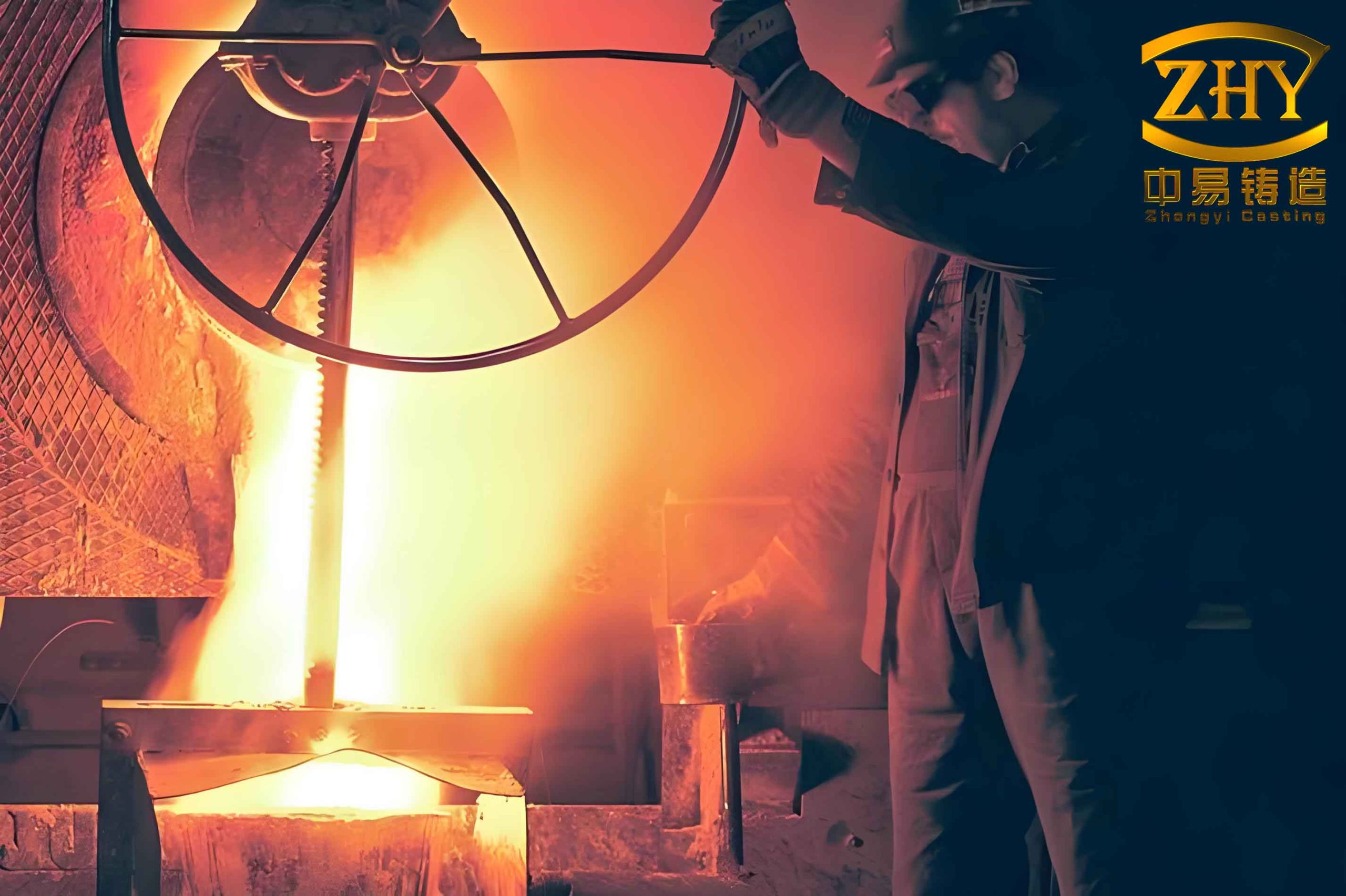
Figure 1 illustrates a typical component produced by high precision investment casting, demonstrating the level of detail achievable with our optimized process. The stiffening bar and auxiliary ribs were later found to be essential for structural integrity.
The modified gating system effectively eliminated hot cracks. The following equations describe the thermal stress factor that we considered:
$$ \sigma_{th} = E \cdot \alpha \cdot \Delta T $$
where \(E\) is Young’s modulus, \(\alpha\) is the coefficient of thermal expansion, and \(\Delta T\) is the temperature difference between the hot and cold regions. By adding the cross-bar, the constrained contraction path was interrupted, reducing the local \(\Delta T\) and consequently the thermal stress.
To compensate for the shrinkage porosity in the T‑region, we modified the shell manufacturing process, as described in the next section.
Shell Manufacturing and Coating
The shell was built using a primary coat containing 50 wt% cobalt aluminate (CoAl₂O₄) as a nucleating agent. This agent refines the surface grain structure and promotes equiaxed solidification, which is known to reduce microporosity. The backup layers were built alternating between ethyl silicate hydrolyzed binder and silica sol binder, with fused alumina or bauxite powders as the refractory filler. A total of eight layers were applied.
Initially, we had problems with shell cracking at the junction between the sprue and the pouring cup due to the relatively small sprue diameter. Operators had to hold the cluster at that narrow region during dipping, causing fatigue. After adding the auxiliary ribs (mentioned above), the shell strength in that area was significantly improved, and handling became safer.
The shell insulation felt wrapping was also optimized. The pouring cup was individually wrapped with two layers of felt, then the entire cluster was wrapped with another two layers. The shell was preheated in a box-type resistance furnace (RX3-75-9) at 950 ± 10 °C before pouring.
Melting and Pouring Parameters
JG4246A superalloy has a narrow liquidus-to-solidus interval and is extremely sensitive to pouring temperature. We conducted experiments with pouring temperatures of 1400 °C, 1430 °C, and 1460 °C (±10 °C), while keeping the refining temperature at 1500 ± 10 °C for 2–3 minutes. The pouring speed was kept high, completing the pour within 2–4 seconds. Based on the defect analysis, we chose the optimal pouring temperature as 1430 ± 5 °C. The melting and pouring process curve is shown conceptually in Figure 2 (not reprinted here, but described in text). Important notes: the mold temperature at pouring should be no less than 900 °C, and the electrical power during melting should be maintained at 10–15 kW to control the melt superheat precisely.
The solidification behavior can be characterized by the feeding distance, which for a plate of thickness \(t\) (mm) can be approximated by:
$$ L_f = k \cdot t^{1/2} $$
where \(k\) is a material-dependent constant. For thin walls (0.8–1.0 mm), the feeding distance is very short, so the gating system must place ingates close to the hot spots. The T‑region, being slightly thicker (about 1.8 mm), has a larger feeding demand. The use of nucleating agent in the primary coat helped to refine the grains and promote interdendritic feeding, thereby eliminating the shrinkage porosity.
Results and Discussion
Table 2 summarizes the qualification rates over five batches after implementing the optimizations described above.
| Batch | Total Castings | Qualified | Qualification Rate (%) | Rejection Causes (Number of pieces) |
|---|---|---|---|---|
| 1 | 30 | 22 | 73.33 | 1 (inclusion), 2 (crack), 3 (crack+inclusion), 1 (crack) |
| 2 | 28 | 21 | 75.00 | 3 (inclusion), 2 (crack), 2 (deformation) |
| 3 | 14 | 13 | 92.86 | 1 (inclusion) |
| 4 | 24 | 18 | 75.00 | 1 (crack), 4 (crack), 1 (inclusion) |
| 5 | 24 | 21 | 87.50 | 1 (inclusion), 2 (inclusion+crack), 1 (crack) |
The overall qualification rate across these batches averaged about 80%, with the later batches (3 and 5) exceeding 87%. The primary defects were still cracks and inclusions, but the occurrence of shrinkage porosity was virtually eliminated after incorporating the nucleating agent in the primary coat. The optimized gating system (with cross-bar) completely suppressed hot tearing at the rib-to-base transitions.
We also performed heat treatment to control the casting flatness. The base plate had a stringent flatness requirement and a stepped geometry. After removing the risers and cleaning, we employed a heat treatment fixture to hot-set the casting at an elevated temperature, which relieved residual stresses and avoided crack formation during straightening.
Key Factors for High Precision Investment Casting Success
From this study, we derived several critical control measures for high precision investment casting of thin-wall superalloy components:
- Gating system design: Use side-gating with additional connecting bars to counteract tensile stresses at thick-thin transitions. Incorporate auxiliary ribs to strengthen the shell assembly.
- Shell coating: Use a nucleating agent (like cobalt aluminate) in the primary coat to refine grain size and reduce shrinkage porosity.
- Pouring parameters: Maintain a narrow pouring temperature window (1430 ± 5 °C) and a fast pour (2–4 s) to minimize temperature drop and oxidation.
- Shell insulation: Wrap the pouring cup separately to avoid premature solidification, and use consistent felt wrapping to control the cooling rate.
- Post-casting treatment: Apply heat treatment with a shape-restraining fixture to achieve the required flatness without introducing new cracks.
The success of this high precision investment casting process lies in the holistic optimization of mold design, shell technology, and melt handling. By integrating these measures, we elevated the casting yield from below 30% to a stable 85% level, while maintaining tight dimensional tolerances and metallurgical integrity.
Conclusion
In this work, we have systematically developed a robust high precision investment casting process for the convergent regulator plate back section made of JG4246A superalloy. Through careful analysis of defect mechanisms, we modified the gating system by adding a horizontal cross-bar and auxiliary ribs, applied a cobalt aluminate nucleating agent in the shell primary coat, and established precise melting and pouring parameters (refining at 1500±10 °C, pouring at 1430±5 °C with rapid fill). The combined improvements eliminated hot cracks and shrinkage porosity, achieving an 85% qualification rate. The methodology and key control points presented here provide a valuable reference for the high precision investment casting of other thin-wall, complex superalloy components in the aero-engine industry.