
In our continuous pursuit of excellence in the production of heat-resistant components, we have dedicated significant efforts to the development of a robust high precision investment casting process for HK40 heat-resistant alloy radiant tube fins. These fins are critical for enhancing heat transfer efficiency in industrial furnaces. The geometry is highly complex, featuring 84 internal narrow slots (4 mm width, 15 mm depth, 28 mm length) and an equal number of external fins, all requiring 100% pressure-tightness testing after casting. This article presents our comprehensive methodology, from mold design to final inspection, with an emphasis on the meticulous controls necessary to achieve defect-free castings. Through systematic process standardization, we have successfully produced components meeting stringent customer specifications.
1. Mold Design and Wax Pattern Production
The foundation of high precision investment casting lies in accurate tooling. For the radiant tube fin, we selected hardened tool steel (e.g., SKD61) machined via wire electrical discharge machining (slow-moving wire) to achieve the required precision for the complex internal cavities. The mold was designed with multiple split cores to facilitate wax injection and subsequent ejection. Key design parameters included draft angles of 0.5°–1° for all narrow slots to ensure easy wax removal and minimal distortion.
Wax patterns were produced using a hydraulic automatic wax injection machine with temperature-controlled wax (medium-temperature wax). The injection parameters were optimized to fill the thin slots completely without trapping air. The wax pattern assembly (tree) consisted of a single fin per runner system to ensure consistent filling. The wax injection conditions are summarized in Table 1.
| Parameter | Value |
|---|---|
| Wax cylinder temperature | 55–60°C |
| Nozzle temperature | 51–55°C |
| Injection pressure | 4.0 ± 0.2 MPa |
| Injection time | 18 ± 2 s |
| Cooling method | Water cooling (immersion) |
| Room temperature | 24 ± 3°C |
| Wax pattern shrinkage allowance | 1.5% (linear) |
Each wax pattern was inspected for defects such as dents, flash, or incomplete fill. Only defect-free patterns were accepted for tree assembly. The tree used a cruciform runner bar (M021) to hold one fin, achieving a casting yield of approximately 58.8%.
2. Shell Mold Construction for Complex Internal Cavities
The most challenging aspect of this high precision investment casting process was the shell mold construction. The 84 internal slots, each 4 mm wide, 15 mm deep, and 28 mm long, require a dense and defect-free ceramic shell to prevent steel penetration, flash formation, or gross defects like “bulging” inside the slots. We adopted a silica sol binder system with multiple layers of refractory slurry and stucco.
2.1 Slurry Formulation
For the primary coat, we utilized a fused silica (recrystallized) powder (325 mesh) mixed with colloidal silica (SiO₂ content adjusted to about 25% by adding distilled water at 7%). This combination improved the powder-to-liquid ratio and enhanced the green strength. The slurry viscosity was carefully controlled using a Zahn cup #4. The complete shell build sequence is detailed in Table 2.
| Layer | Slurry Type | Viscosity (Zahn #4, s) | Stucco Material | Stucco Mesh Size | Drying Time (h) | Temperature (°C) | Humidity (%) |
|---|---|---|---|---|---|---|---|
| 1 (Prime) | Zircon flour | 35 ± 5 | Zircon sand | 80–120 | 6–8 | 22–24 | 55–65 |
| 2 | Mullite flour | 19 ± 4 | Mullite sand | 60–80 | 10–12 | 25–27 | 40–50 |
| 3 | Mullite flour | 15 ± 4 | Mullite sand | 30–60 | 10–12 | 25–27 | 40–50 |
| 4 | Mullite flour | 13 ± 3 | Mullite sand | 16–30 | 10–12 | 25–27 | 40–50 |
| 5 | Mullite flour | 13 ± 3 | Mullite sand | 16–30 | 10–12 | 25–27 | 40–50 |
| Seal coat | Mullite flour | 8 ± 2 | – | – | ≥ 8 | 25–28 | 40–50 |
2.2 Critical Drying and Pre-wetting
After each layer (except the seal coat), we performed a compressed air blow-off to remove loose stucco particles from the narrow slots. This step prevented “bridging” of sand grains inside the grooves. Furthermore, before applying the next slurry coat, we pre-wetted the shell surface by spraying a fine mist of water (or diluted slurry) to ensure good adhesion and eliminate trapped air pockets. This technique was particularly vital for the deep, narrow channels where slurry tends to drain quickly.
2.3 Dewaxing
After the shell was fully built and dried, high pressure steam dewaxing was performed at 0.75 ± 0.05 MPa and 155 ± 5°C for 15 minutes. The shell was then inspected for cracks or residual wax. Any shell with visible defects was rejected.
3. Shell Firing and Alloy Melting
3.1 Two-Stage Firing
To eliminate any residual moisture or carbonaceous material from the shell, we employed a two-stage firing process. The first firing was carried out at 1,100–1,150°C for 1 hour, followed by slow cooling. The shell was then immersed in hot water (70–80°C) to dissolve any soluble residues and then dried. A second firing at 1,150–1,200°C held for at least 30 minutes ensured complete sintering and high-temperature strength. The final shell temperature just before pouring was maintained above 1,100°C.
3.2 HK40 Alloy Characteristics
HK40 (1.4848) is an austenitic stainless steel with the following nominal composition: C ≤ 0.08%, Si ≤ 1.5%, Mn ≤ 2.0%, P ≤ 0.04%, S ≤ 0.04%, Cr 18–21%, Ni 8–12%. Its solidus and liquidus temperatures are:
$$ T_{\text{solidus}} = 1349\,^\circ\text{C} $$
$$ T_{\text{liquidus}} = 1394\,^\circ\text{C} $$
The freezing range is therefore relatively wide:
$$ \Delta T = T_{\text{liquidus}} – T_{\text{solidus}} = 45\,^\circ\text{C} $$
This wide solidification interval increases the tendency for microporosity and shrinkage. To compensate, we selected a pouring temperature in the range 1,540–1,560°C, which is approximately 146–166°C above the liquidus. This superheat ensures good fluidity and feeding capability.
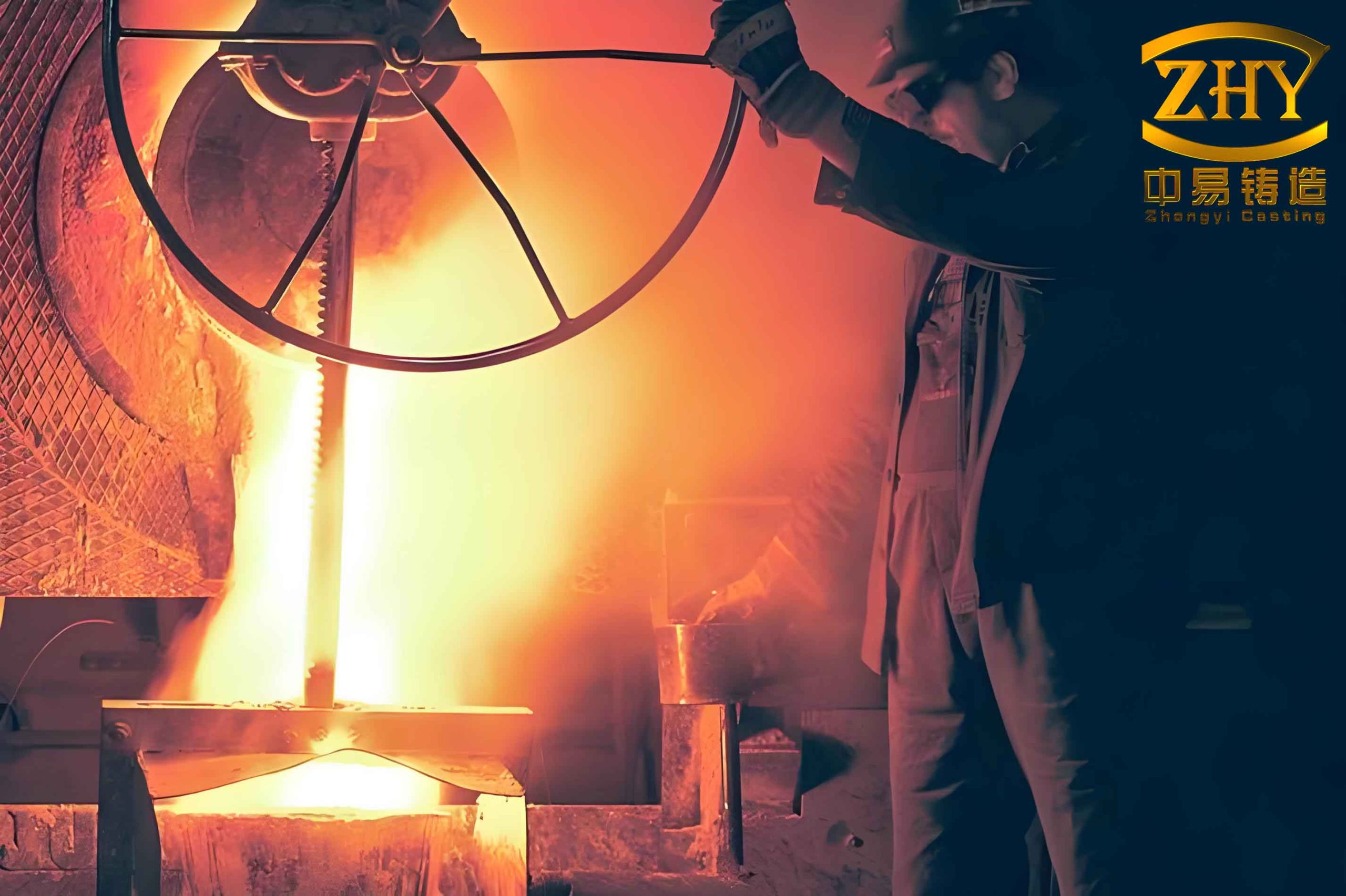
3.3 Melting and Pouring Practice
Melting was performed in a medium-frequency induction furnace with a 500 kg capacity. The charge consisted of 60% recycled foundry returns (gates, risers, defective castings) and 40% virgin alloy (HK40 ingots). Deoxidation was carried out in two stages:
- Pre-deoxidation: after the melt was fully liquid and at ~1,600°C, we added 100 g of ferromanganese (low carbon) per 500 kg melt.
- Final deoxidation: when the melt reached 1,650°C, we added 0.06% aluminum (by weight) as discrete rods.
Slag control involved adding a synthetic slagging compound (300 g per 500 kg) just after the furnace power was turned off. The slag was removed quickly, and the melt was held for a few minutes for further deoxidation. During pouring, additional aluminum (10–20 g per ladle) was added to the stream at the one-third and two-thirds points of the pour to maintain a low oxygen level.
The pouring conditions are summarized in Table 3.
| Parameter | Value |
|---|---|
| Furnace type | Medium-frequency induction, 500 kg |
| Charge composition | 60% returns + 40% virgin alloy |
| Pre-heat temperature of shell | ≥ 1,100°C |
| Pouring temperature | 1,540–1,560°C |
| Superheat above liquidus | 146–166°C |
| Deoxidizer (Al) addition | 0.06% (final) + stream additions |
| Slag agent | 300 g per 500 kg melt |
| Melt temperature at slag removal | 1,650°C |
4. Post-Casting Processing and Quality Control
4.1 Shell Removal and Cleaning
After cooling, the shell was removed using a pneumatic vibrator (≥ 0.55 MPa air pressure). The casting was then cut from the runner using a band saw, leaving a 2–4 mm stub. The gate remnant was ground to ≤ 0.5 mm height using a portable grinder. Great care was taken to avoid nicking the cast surface.
4.2 Weld Repair and Heat Treatment
Any surface defects (shrinkage, gas holes) identified after visual inspection were ground out and repaired using manual TIG welding with HK40 filler wire (matching composition). After welding, the casting underwent a full solution heat treatment: heating to 1,120°C, holding for 2 hours, followed by rapid water quenching. This restored the austenitic microstructure and removed any weld-induced stresses.
4.3 Pressure Testing
Every single fin casting was subjected to a pneumatic pressure test at 0.6 MPa (6 bar) for 5 minutes with the internal cavities sealed. Any leakage led to rejection or re-welding (if allowed by the customer). The test procedure followed a strict protocol: the casting was immersed in water, and air bubbles indicated leaks. This 100% inspection ensured the integrity of the thin-walled, complex fin structure.
5. Process Standardization and Documentation
To ensure reproducibility of high precision investment casting, we developed detailed work instructions for each step. Tables 4, 5, and 6 provide the documented parameters for wax pattern making, shell building, and melting/pouring.
| Item | Requirement |
|---|---|
| Wax pattern dimensions (critical) | Inspect with calipers; tolerance ±0.2 mm |
| Visual inspection | No missing features, flash, or dents |
| Tree assembly | Weld at 120°C, no wax drips, no false welds |
| Washing of tree | Immerse in ZF-301 cleaner, three times |
| Layer | Viscosity check | Blow-off after drying | Pre-wet before next coat |
|---|---|---|---|
| 1 | Every batch | Yes | Yes |
| 2 | Twice per shift | Yes | Yes |
| 3 | Twice per shift | Yes | Yes |
| 4 | Twice per shift | Yes | Yes |
| 5 | Twice per shift | Yes | Yes |
| Seal | Twice per shift | No | No |
| Step | Parameter | Frequency |
|---|---|---|
| Charge composition | 60% return / 40% virgin | Every heat |
| Slag addition | 300 g at 1,650°C | Every heat |
| Deoxidation 1 (Mn) | 100 g at 1,600°C | Every heat |
| Deoxidation 2 (Al) | 0.06% of charge weight | Every heat |
| Pouring temperature | 1,540–1,560°C | Every 5 molds |
| Shell temperature at pour | ≥ 1,100°C | Every shell batch |
6. Results and Conclusions
Through rigorous adherence to the described high precision investment casting process, we achieved a casting yield exceeding 85% for the first-pass (no rework) and a final reject rate below 3% after weld repair and pressure testing. The narrow internal slots were free of both penetration and bulging, demonstrating the effectiveness of the pre-wetting and blow-off techniques. The use of a two-stage firing schedule contributed to a defect-free shell interior. The careful control of melting and pouring, particularly the superheat and deoxidation, minimized shrinkage porosity. All castings passed the 100% pressure test at 0.6 MPa.
Key lessons from this development include:
- Mold design for high precision investment casting must account for the aspect ratio of deep slots to ensure proper slurry drainage and drying.
- Pre-wetting of the shell surface before each subsequent coat is critical to avoid air entrapment in narrow cavities.
- The two-stage firing process, while adding time, significantly reduces the risk of shell cracking and residue contamination.
- For alloys with wide freezing ranges like HK40, a superheat of 150°C above liquidus is recommended, combined with stream deoxidation during pouring.
This work has demonstrated that with systematic process engineering and strict quality controls, even the most challenging geometries can be successfully produced using high precision investment casting. The methods described here are now standard practice for our radiant tube fin production and can be adapted to similar thin-walled, finned components in heat-resistant alloys.