
In my experience as a casting engineer, the production of large-scale components like driving wheels for agricultural machinery presents significant challenges, particularly when using nodular cast iron, which requires precise control over microstructure and defect formation. This article details the comprehensive process improvements undertaken to manufacture a driving wheel made of nodular cast iron, specifically grade GGG60 according to DIN 1693, with a focus on eliminating internal shrinkage and surface porosity defects. The wheel, with an outer diameter of 916 mm, height of 526 mm, and mass of 260 kg, features 19 evenly spaced teeth around its circumference. Each tooth root acts as an isolated hot spot, and due to functional requirements, the teeth cannot have any draft angle, complicating the molding process. The internal quality must meet radiographic inspection Level 2, and destructive testing allows for shrinkage porosity less than 12.7 mm in diameter within a 38.1 mm × 38.1 mm area. Surface quality permits pores up to 2 mm in diameter, with no more than 5 in any 38.1 mm × 38.1 mm region. The use of nodular cast iron is critical here due to its excellent mechanical properties, but it is prone to shrinkage defects if not properly risered and cooled.
The initial molding process design involved a split along the central plane perpendicular to the axis, using symmetrical molding. To address the zero-draft requirement on the teeth, a core assembly strategy was adopted. Each tooth was formed by assembling two sub-cores (labeled 1# and 2#) into a larger core (3#). Three of these 3# cores were then placed into positioning cores (4# and 5#) to form a segment core (6#), and six such segment cores were arranged in the drag mold. The upper and lower molds were made with resin sand, while the 1#, 2#, 4#, and 5# cores were produced using hot-box coated sand. This approach minimized fins and ensured accurate tooth profiles, but as simulations later revealed, it did not adequately address solidification issues inherent in nodular cast iron.
To predict and mitigate defects, I employed ProCAST simulation software. The initial simulation, based on a central gating system, indicated severe shrinkage porosity at the center of each tooth, exceeding the allowable limits. The porosity volume was calculated using the Niyama criterion, which relates thermal gradients to shrinkage formation. For nodular cast iron, the critical Niyama value $N_y$ is given by:
$$N_y = \frac{G}{\sqrt{\dot{T}}}$$
where $G$ is the temperature gradient (K/mm) and $\dot{T}$ is the cooling rate (K/s). Regions with $N_y$ below a threshold (typically around 1 °C1/2·mm-1/2·s1/2 for nodular cast iron) are prone to microporosity. The simulation showed $N_y$ values below 0.5 in the tooth centers, confirming shrinkage risk. After multiple iterative simulations, it became evident that adding risers above each tooth could provide effective feeding, and placing chills at the tooth bottoms would reduce the hot spot size by accelerating cooling. The revised design included 19 risers, one per tooth, connected via a horizontal runner, with chills placed in the drag mold beneath each tooth.
The riser design was based on modulus method calculations to ensure adequate feeding for the nodular cast iron. For each tooth, the casting weight $G_c$ is 4.44 kg, volume $V_c = 6.03 \times 10^{-4} \, \text{m}^3$, and surface area $A_c = 5.58 \times 10^{-2} \, \text{m}^2$. The modulus $M_c$ is:
$$M_c = \frac{V_c}{A_c} = 1.08 \times 10^{-2} \, \text{m}$$
The mass boundary quotient $Q_m$ is:
$$Q_m = \frac{G_c}{M_c^3} = 3.52 \times 10^3 \, \text{kg/m}^3$$
For a pressure-controlled riser, the riser body modulus $M_R$ is calculated as:
$$M_R = f_1 \cdot f_2 \cdot f_3 \cdot M_c$$
where $f_1 = 1.19$ (feeding factor), $f_2 = 0.76$ (material factor for nodular cast iron), and $f_3 = 1.2$ (shape factor). Thus:
$$M_R = 1.19 \times 0.76 \times 1.2 \times 1.08 \times 10^{-2} = 1.17 \times 10^{-2} \, \text{m}$$
The riser neck modulus $M_N$ is:
$$M_N = f_p \cdot f_4 \cdot M_R$$
with $f_p = 0.65$ (pressure factor) and $f_4 = 0.9$ (neck factor), giving:
$$M_N = 0.65 \times 0.9 \times 1.17 \times 10^{-2} = 0.68 \times 10^{-2} \, \text{m}$$
This corresponds to a neck diameter of 52 mm. For a cylindrical blind riser with aspect ratio $K = H/D = 1.8$, the dimensions were selected as 80 mm diameter and 120 mm height. The gating system was modified to connect a horizontal runner to these risers, with ingates linking risers to the casting. Pouring temperature was set at 1355–1365 °C to maintain fluidity while minimizing gas absorption in nodular cast iron.
| Property | Required Value | Typical Range for Nodular Cast Iron |
|---|---|---|
| Tensile Strength | ≥ 600 MPa | 600–900 MPa |
| Yield Strength | ≥ 370 MPa | 370–600 MPa |
| Elongation | ≥ 3% | 3–20% |
| Hardness (HBW) | 187–269 | 187–300 |
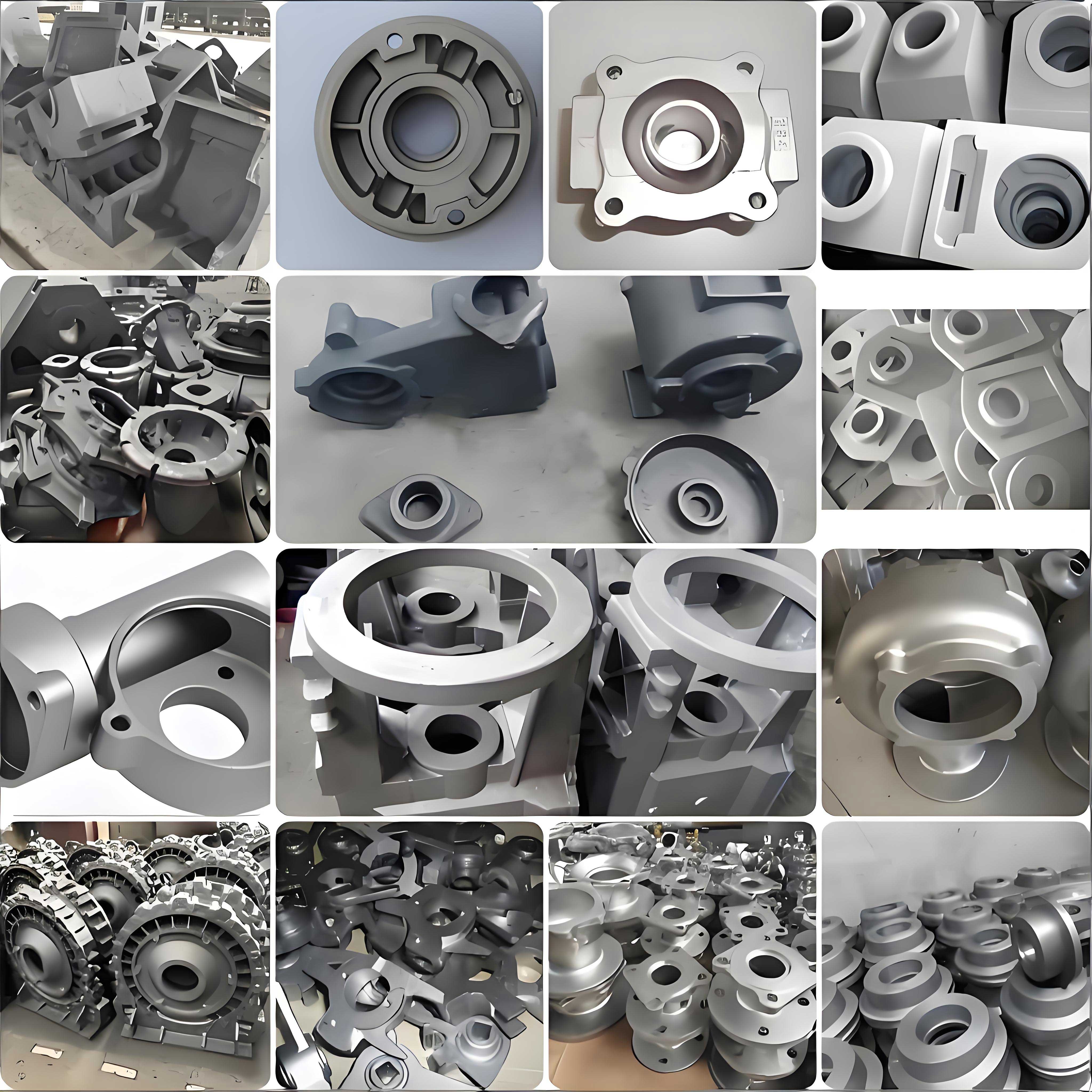
After implementing these changes, trial castings were produced and destructively tested. The sectional analysis showed that shrinkage porosity was eliminated in most teeth, with only minor micro-porosity in a few upper regions, well within specification limits. However, surface blowhole defects emerged, primarily distributed along the tooth faces and inner walls, as seen in the image below. This was attributed to high gas evolution from the coated sand cores, exacerbated by the thin-walled sections of the teeth hindering venting. The total gas volume $V_g$ generated can be estimated using the formula:
$$V_g = \sum_{i} (m_i \cdot g_i)$$
where $m_i$ is the mass of core i and $g_i$ is its specific gas evolution rate (ml/g). For standard coated sand, $g_i$ ranges from 10–20 ml/g, but for nodular cast iron castings, even small amounts of gas can cause pores due to the rapid solidification skin formation.
To address surface porosity, I introduced several corrective measures focused on reducing gas generation and improving ventilation. First, the 1# and 2# cores were made with coarser 50/100 mesh sand to lower the specific surface area and thus gas evolution. The gas evolution rate $g$ correlates with sand fineness number $GFN$ as:
$$g \propto \frac{1}{GFN^{0.5}}$$
so increasing grain size reduces $g$. Second, all assembled 6# core segments were baked in an oven at 180 °C for 4 hours to remove residual moisture and volatiles. The drying kinetics can be described by Fick’s second law for diffusion:
$$\frac{\partial C}{\partial t} = D \frac{\partial^2 C}{\partial x^2}$$
where $C$ is moisture concentration, $D$ is diffusivity, and $x$ is depth. Baking reduces $C$ at the core surface, minimizing gas pressure during pouring. Third, additional vent channels were incorporated into the mold design, particularly around the tooth cores, to facilitate gas escape. The venting capacity $Q_v$ was calculated based on ideal gas law:
$$Q_v = \frac{nRT}{P}$$
where $n$ is moles of gas, $R$ is gas constant, $T$ is temperature, and $P$ is pressure. By increasing vent cross-sectional area by 30%, $Q_v$ was enhanced to handle peak gas evolution rates typical in nodular cast iron processing.
| Aspect | Initial Process | Improved Process | Impact on Nodular Cast Iron Quality |
|---|---|---|---|
| Tooth Formation | Zero-draft, simple cores | Core assembly with 1# and 2# sub-cores | Reduced fins, accurate geometry |
| Feeding System | Central gating, no risers | 19 risers (Ø80 mm ×120 mm) with chills | Eliminated shrinkage porosity |
| Core Sand | Standard coated sand | Coarse 50/100 sand for 1# and 2# cores | Lower gas evolution |
| Core Treatment | No baking | Baking at 180°C for 4 hours | Reduced moisture and volatiles |
| Venting | Basic vents | Enhanced vent channels | Improved gas escape |
Following these modifications, over 120 driving wheels were cast successfully. The surface quality improved dramatically, with no blowholes detected, and internal integrity met radiographic standards. The nodular cast iron microstructure exhibited well-formed graphite spheroids with ferritic-pearlitic matrix, as required for GGG60. The mechanical properties were validated through tensile testing, with averages of 650 MPa tensile strength, 400 MPa yield strength, 8% elongation, and 220 HBW hardness, all within specified ranges for nodular cast iron.
In conclusion, the integration of core assembly design, systematic riser and chill placement based on modulus calculations, and targeted gas reduction measures proved effective for producing high-integrity nodular cast iron driving wheels. The use of simulation tools like ProCAST was invaluable for optimizing the process, particularly in predicting shrinkage behavior in nodular cast iron. Key lessons include the importance of customizing riser design for isolated hot spots and the need to manage gas evolution from cores in thin-section nodular cast iron castings. Future work could explore advanced feeding aids or alternative core materials to further enhance yield and surface finish for nodular cast iron components.
The success of this project underscores the versatility of nodular cast iron in heavy-duty applications, provided that casting processes are meticulously engineered. By balancing thermal management through chills and risers, and controlling gas generation via core treatment, consistent quality can be achieved. This approach is applicable to other complex nodular cast iron castings with similar geometric challenges, contributing to the advancement of casting technology for durable machinery parts.