
In modern industrial manufacturing, the demand for durable and reliable components is paramount, especially for safety-critical parts. Among these, brake drums for commercial vehicles represent a significant application where material performance directly impacts operational safety and lifecycle costs. The primary material of choice for these components has long been grey iron castings, valued for their unique combination of properties. However, a persistent challenge faced by these castings under severe service conditions is premature failure due to thermal fatigue cracking. This article explores, from a first-person research and development perspective, an advanced metallurgical approach aimed at fundamentally enhancing the performance of grey iron castings for brake drums through a process known as graphite end passivation.
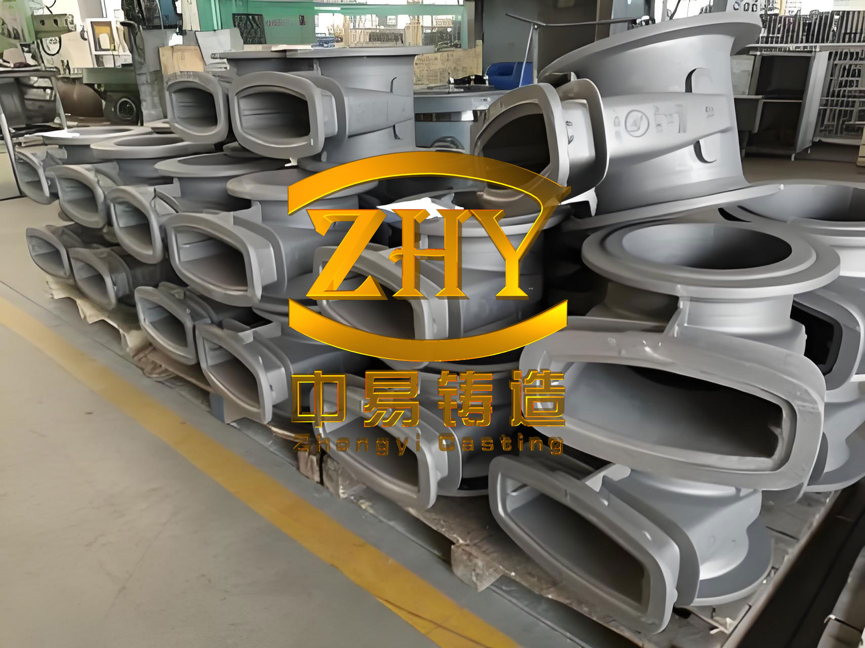
Grey iron castings are indispensable Fe-C-Si ternary alloys, offering an exceptional balance of wear resistance, thermal stability, damping capacity, and machinability. Their relatively low melting point, excellent castability, and cost-effectiveness make them ideal for high-volume production of complex shapes like brake drums. The performance and service life of these grey iron castings are predominantly governed by their microstructure—specifically, the morphology of the graphite flakes embedded within the metallic matrix. The traditional strength-thermal conductivity trade-off in grey iron castings often forces a compromise. High-strength grades with lower carbon equivalent (CE) offer good mechanical properties but inferior thermal conductivity, making them prone to heat accumulation and thermal cracking. Conversely, high-carbon equivalent (CE ≥ 3.9%) grey iron castings exhibit superior thermal conductivity and damping but suffer from lower tensile strength due to the increased amount and sharp-ended morphology of the graphite flakes, which act as stress concentrators and crack initiators.
The core of the problem lies in the natural growth habit of graphite in grey iron castings. Under standard solidification conditions, graphite precipitates as sharp, platelet-like flakes. The tips of these flakes are acutely pointed, creating regions of high stress concentration under mechanical or thermal load. During repeated braking cycles, the brake drum experiences rapid and severe thermal fluctuations. This thermal cycling induces stresses that readily concentrate at these sharp graphite tips, leading to the nucleation and propagation of microcracks, eventually culminating in catastrophic failure. Therefore, the pursuit of enhanced performance in grey iron castings for brake drums has focused on modifying this inherent graphite morphology.
Graphite Passivation: Concept and Classification
The proposed technological solution centers on the concept of “graphite passivation.” In this context, passivation does not refer to a surface chemical treatment but rather to a metallurgical modification of the graphite shape during solidification. The objective is to transform the sharp, stress-concentrating tips of the graphite flakes into rounded, blunted ends. This morphological change significantly reduces the stress concentration factor (K_t) at the graphite/matrix interface, thereby hindering crack initiation and improving both the static strength and, more critically, the thermal fatigue resistance of the grey iron castings.
Passivated graphite structures can be systematically classified based on the degree of tip rounding. This classification is essential for quantitative quality control.
| Passivation Class | Morphological Description | Status |
|---|---|---|
| Class I | Graphite flakes with both ends fully rounded/blunted; low aspect ratio (length/width); short and stubby appearance. | Fully Passivated |
| Class II | Graphite flakes with both ends rounded/blunted, no sharp edges; higher aspect ratio than Class I. | Fully Passivated |
| Class III | Graphite flakes with one end rounded and the opposite end sharp/pointed; typically high aspect ratio. | Partially Passivated |
| Class IV | Graphite flakes with both ends sharp and pointed; conventional untreated graphite morphology. | Non-Passivated |
The quantitative assessment of treatment effectiveness is given by the Graphite Passivation Rate (GPR). It is measured on polished (unetched) samples at 200x magnification, excluding graphite intersected by the field boundary. The formula for calculation is:
$$ GPR = \frac{N_I + N_{II} + 0.5 \times N_{III}}{N_{Total}} \times 100\% $$
where \( N_I \), \( N_{II} \), and \( N_{III} \) are the counts of Class I, II, and III graphite flakes, respectively, and \( N_{Total} \) is the total number of graphite flakes counted in the field of view. A minimum of five fields are averaged for a representative result. The target for high-performance grey iron castings is to maximize this GPR value.
Material Design and Alloying Strategy for Passivation
The goal is to produce high-carbon equivalent (CE ~ 4.0-4.1%) grey iron castings with enhanced strength. This requires active intervention in the solidification process to alter graphite growth kinetics. Our approach combines microalloying with rare earth (RE) elements and controlled nitrogen (N) addition.
Role of Rare Earth (RE) Elements: When added in trace amounts (typically < 0.1 wt.%), rare earth elements like La and Ce play a multifaceted role. They are powerful desulfurizers and deoxidizers, forming stable compounds that purify the melt. More importantly, they adsorb at the growing interface of the graphite crystal. It is theorized that RE adsorption lowers the interfacial energy between the graphite basal plane and the iron melt, promoting growth via a spiral dislocation mechanism normal to the basal plane rather than rapid lateral extension. This results in graphite that is finer, more curved, and crucially, with blunted tips. Furthermore, RE elements contribute to matrix refinement by promoting a finer pearlitic structure.
Role of Nitrogen (N): Nitrogen, within a precise optimal range, is a potent graphite modifier. During solidification, nitrogen atoms are adsorbed at the advancing growth fronts (particularly the edges) of the graphite flakes. This adsorption and possible interstitial solid solution in graphite impede its growth along certain crystallographic directions. The consequences are a reduction in the flake aspect ratio, increased branching and curvature, and a blunting of the sharp edges. Concurrently, nitrogen enhances the pearlite content and refines its lamellar spacing. The beneficial window for nitrogen in these grey iron castings is narrow, typically between 90-120 ppm. Sub-optimal levels yield no effect, while excess nitrogen leads to gas porosity (nitrogen pin-holes), severely degrading the integrity of the castings.
The synergy of RE and N can be conceptually represented by their effect on the growth restriction factor and undercooling. The combined effect can be modeled to a first approximation by considering their influence on the interfacial stability parameter. The modified growth velocity \( v_g \) of a graphite tip might be related to its radius of curvature \( r \) and a solute-dependent factor:
$$ v_g \propto \frac{\Delta T}{\Gamma \cdot r} \cdot f([RE], [N]) $$
where \( \Delta T \) is the undercooling, \( \Gamma \) is the Gibbs-Thomson coefficient, and \( f([RE], [N]) \) is a function describing the retardation due to solute adsorption at the interface. The net effect is a transition from planar or sharply dendritic growth to a more isotropic, rounded growth form.
The base composition for producing these advanced grey iron castings is designed to maintain high CE while allowing for effective microalloying.
| Element | Target Range (wt.%) | Rationale |
|---|---|---|
| C | 3.40 – 3.50 | Primary contributor to CE, graphite formation, and thermal conductivity. |
| Si | 1.75 – 1.90 (Final) | Promotes graphitization, increases fluidity. Si/C ratio is raised to ~0.5-0.6. |
| Mn | 0.70 – 1.05 | Counteracts sulfur, promotes pearlite. Final level increases with N addition via MnN. |
| P | ≤ 0.05 | Minimized to avoid phosphide eutectic, which embrittles the casting. |
| S | 0.008 – 0.012 | Low level is essential prior to RE treatment to avoid excessive RE consumption as sulfides. |
| Cr | 0.30 – 0.60 | Pearlite stabilizer, enhances hardness and wear resistance. |
| Cu | 0.40 – 0.60 | Strengthens matrix, refines pearlite, improves corrosion resistance. |
The Carbon Equivalent (CE) is calculated as: $$ CE = \%C + \frac{\%Si + \%P}{3} $$. Our target is CE ≥ 3.9%.
Production Process and Experimental Methodology
The investigation was conducted on industrial-scale production of commercial vehicle brake drums. The process flow was meticulously designed to implement and test the graphite passivation technology.
1. Melting and Base Iron Preparation: A 6-ton medium-frequency induction furnace was used. The charge consisted of steel scrap and synthetic graphite to achieve the target carbon content. The aim was to produce a base iron with controlled low sulfur. The tapping temperature was maintained at 1,520 – 1,540°C to ensure sufficient superheat for subsequent treatment and casting.
2. Treatment Sequence in the Transfer Ladle: Single batches of 1,500 kg were treated.
- Nitrogen Addition: Immediately after tapping, a predetermined amount of manganese nitride (MnN) was added to the stream of iron entering the treatment ladle. The MnN addition serves the dual purpose of introducing nitrogen and increasing manganese content.
- Wire-Injection Passivation Treatment: This is the core step. A cored wire containing the reactive inoculant/passivator was injected into the ladle using an automated wire-feeding system. The wire composition is critical.
| Component | Content (wt.%) |
|---|---|
| Si | 40-50 |
| Ca | 2-3 |
| Ba | 5-8 |
| RE (Rare Earth) | 20-30 |
| Al | ≤ 1.0 |
| Fe | Balance |
- Post-Inoculation: Following wire injection, the iron was transferred to a pouring ladle, during which a secondary inoculation with a conventional FeSi-based inoculant (containing Ca, Al) was performed to combat fading and ensure a uniform fine graphite distribution.
3. Molding and Casting: The brake drums were produced on a high-pressure molding line with a two-cavity mold per pattern. A bottom-gating system was employed to ensure smooth, turbulent-free filling. The pouring temperature was controlled between 1,400 – 1,420°C. A late-stream inoculation was added during pouring to maintain nucleation potency until the moment of solidification.
To establish the optimal treatment parameters, five distinct trial conditions (batches 1# to 5#) were executed with varying addition levels of passivation wire and MnN, as detailed below. All other process parameters were held constant.
| Batch No. | Passivation Wire Addition (wt.%) | MnN Addition (wt.%) |
|---|---|---|
| 1# | 0.20 | 0.10 |
| 2# | 0.30 | 0.20 |
| 3# | 0.40 | 0.30 |
| 4# | 0.50 | 0.35 |
| 5# | 0.60 | 0.40 |
The final chemical compositions for the different batches, particularly the RE and N levels achieved, are presented below. This data is crucial for correlating composition with performance.
| Element (wt.%) | Batch 1# | Batch 2# | Batch 3# | Batch 4# | Batch 5# |
|---|---|---|---|---|---|
| C | 3.42 | 3.42 | 3.41 | 3.42 | 3.41 |
| Si | 1.79 | 1.81 | 1.83 | 1.85 | 1.86 |
| Mn | 0.76 | 0.83 | 0.90 | 1.01 | 1.04 |
| P | 0.023 | 0.023 | 0.022 | 0.023 | 0.022 |
| S | 0.010 | 0.011 | 0.010 | 0.0098 | 0.010 |
| Cr | 0.44 | 0.45 | 0.46 | 0.45 | 0.44 |
| Cu | 0.46 | 0.46 | 0.458 | 0.46 | 0.46 |
| RE | 0.016 | 0.024 | 0.033 | 0.042 | 0.053 |
| N (ppm) | 78 | 96 | 114 | 120 | 132 |
| CE | ~4.03 | ~4.04 | ~4.03 | ~4.06 | ~4.05 |
Results, Analysis, and Discussion
1. Mechanical Performance: Tensile specimens (Φ10 mm) and hardness samples were taken from the cast brake drums. The results demonstrate a clear trend related to the treatment intensity.
| Batch No. | Tensile Strength (MPa) | Brinell Hardness (HBW) | Passivation Rate (GPR, %) |
|---|---|---|---|
| 1# | 239 | 195 | ~20 |
| 2# | 263 | 202 | ~30 |
| 3# | 284 | 213 | ~35 |
| 4# | 292 | 223 | ~40 |
| 5# | 280 | 200 | ~20 |
The data reveals a significant finding: mechanical properties and passivation rate do not increase monotonically with additive amount. There exists a distinct optimum. Batches 1# through 4# show progressive improvement in strength, hardness, and GPR. This correlates directly with increasing RE and N levels, which refine the graphite morphology and the pearlitic matrix. The matrix strength can be related to pearlite interlamellar spacing \( \lambda \) by a Hall-Petch type relationship: $$ \sigma_y \propto \frac{k}{\sqrt{\lambda}} $$ where \( k \) is a constant. The blunted graphite reduces the effective stress concentration, allowing the strengthened matrix to bear higher loads before failure, thus increasing the overall tensile strength of the grey iron castings.
However, Batch 5#, with the highest addition levels (0.053% RE, 132 ppm N), exhibits a marked decline in all measured properties. This indicates that the optimal window has been exceeded.
2. Metallographic Analysis and Mechanism: The microstructural evolution provides the explanation for the mechanical property trends. The micrographs show a clear progression:
- Batch 1# & 2#: Graphite shows initial signs of modification—slight curvature and the beginning of tip rounding. The matrix is predominantly pearlite, but refinement is moderate.
- Batch 3#: Graphite is noticeably shorter, thicker, and more curved. The proportion of rounded tips increases. The pearlite is significantly refined.
- Batch 4# (Optimum): The most desirable microstructure. Graphite flakes are distinctly short, stubby, and highly curved with a high percentage of fully blunted ends (Classes I & II). The pearlite matrix is very fine and dense. This structure maximizes the GPR (~40%) and provides the best combination of strength and thermal stress relief.
- Batch 5# (Over-treated): The microstructure deteriorates. Graphite appears less modified than in Batch 4#, with a lower GPR. More critically, the casting process itself was affected; the fluidity of the iron was noticeably reduced, leading to mist runs in late-poured molds. Machined surfaces revealed subsurface porosity. The excessive RE and N have negatively impacted the casting’s integrity.
The decline in Batch 5# can be attributed to several factors. Excess RE forms high-melting-point clusters (e.g., RE-oxysulfides) that can act as inclusions and increase melt viscosity. Nitrogen beyond its solubility limit leads to the formation of molecular nitrogen gas bubbles during solidification, creating micro-porosity. This porosity severely undermines the effective load-bearing area and acts as a potent stress raiser itself, negating the benefits of graphite passivation. The relationship between ultimate tensile strength (UTS), porosity fraction \( f_p \), and graphite morphology can be conceptually described by: $$ UTS \approx \sigma_0 \cdot (1 – f_p)^{n} \cdot \psi(GPR) $$ where \( \sigma_0 \) is the matrix strength, \( n \) is an empirical constant, and \( \psi(GPR) \) is a function increasing with the Graphite Passivation Rate. For Batch 5#, the increase in \( f_p \) outweighs any potential gain from \( \psi(GPR) \).
Conclusions and Outlook
This investigation into graphite passivation technology demonstrates a viable and effective pathway for manufacturing superior performance grey iron castings, specifically for demanding applications like brake drums. The key conclusions are:
- Graphite end passivation via controlled additions of rare earth elements and nitrogen is a potent method to enhance the mechanical properties of high-carbon equivalent grey iron castings. It successfully decouples the traditional trade-off, allowing for improved tensile strength and hardness while maintaining high thermal conductivity.
- The improvement mechanism is twofold: (a) Morphological modification of graphite from sharp flakes to blunted, curved forms, drastically reducing stress concentration factors; and (b) Refinement of the pearlitic matrix, increasing its inherent strength.
- There exists a critical optimum addition range for both RE and N. For the specific production setup and base iron chemistry studied, the optimum was found at a passivation wire addition of ~0.5% and MnN addition of ~0.35%, yielding a final composition of approximately 0.042% RE and 120 ppm N. This resulted in a graphite passivation rate of ~40%, a tensile strength of 292 MPa, and a hardness of 223 HB at a CE > 4.0%.
- Exceeding the optimal addition levels is detrimental. It leads to reduced melt fluidity, increased risk of gas porosity (nitrogen pinholes), and a consequent decline in both mechanical properties and casting soundness. This underscores the necessity for precise process control.
The successful implementation of this technology provides a robust technical foundation for producing next-generation brake drums with extended service life and enhanced resistance to thermal fatigue failure. Future work should focus on modeling the precise kinetic and thermodynamic interactions of RE and N at the solid/liquid interface, optimizing the treatment for different section sizes of grey iron castings, and conducting full-scale dynamometer and field testing to quantify the improvement in thermal fatigue cycles to failure. The principles of graphite morphology control explored here also hold promise for other applications of grey iron castings where reliability under cyclic loading is critical.