
The coupler is one of the most important components connecting train carriages and locomotives, playing a role in connecting trains and ensuring safe operation. The investment casting locomotive coupler transmits the tensile and compressive loads borne by adjacent vehicles. When the train starts or brakes, the investment casting locomotive coupler device between adjacent carriages will experience significant longitudinal impact. If the longitudinal instantaneous stress exceeds the limit value of investment casting locomotive hook, it will damage the investment casting locomotive hook device and even the carriage structure, leading to serious accidents; If used for a long time, investment casting locomotive couplers are prone to fatigue under alternating loads, leading to fatigue fracture and safety accidents.
Given the importance of investment casting for locomotive couplers, investment casting production must ensure that investment casting locomotive couplers have sufficient strength and fatigue life. Therefore, scholars have conducted extensive research on the fatigue performance of investment casting locomotive couplers. To predict the fatigue life of investment casting locomotive couplers, Tian Changliang et al. conducted rotational bending fatigue tests and measured the fatigue limits of three different strength and toughness matched 25MnCrNiMoA steels. The study showed that strength and toughness have a significant impact on the high cycle fatigue behavior of heavy-duty locomotive coupler materials. Meng Qingmin et al. monitored the crack propagation process of 20 in-service investment casting locomotive hook tongues of freight cars, and obtained the relationship between the remaining life and the corresponding crack length based on a 95% survival rate and a 90% confidence level. Zhu Tao et al. used the load spectrum obtained from line measurements as the service environment for heavy-duty freight car couplers, conducted fatigue bench tests, and fitted the degradation data of investment casting locomotive couplers based on hypothetical distributions to obtain a life prediction chart.
Studying the fatigue crack propagation and life of investment casting locomotive couplers through fatigue tests has the advantages of being intuitive and accurate, but it is also time-consuming and laborious. Estimating the fatigue life through a combination of theory and simulation is fast and effective. Wu Gang et al. used the Palmgren Miner cumulative fatigue damage criterion to conduct fatigue analysis on the life cycle of investment casting locomotive hook buffer devices.
MOHAMMADI et al. successfully predicted the fatigue life of investment cast locomotive couplers under different working conditions using various methods, including the critical surface method. Yin et al. proposed a reliability analysis method for heavy-duty truck hook bodies based on SMOTE Bootstrap Bayes estimation, which has important theoretical and practical value for improving the utilization of test data, reducing test costs, and effectively evaluating the fatigue life of hook bodies. Ren et al. established a finite element model under real contact constraints, predicted the remaining life based on Paris law and NASGRO equation, and proposed inspection cycle recommendations for cast steel heavy-duty car hooks.
In summary, it is necessary and economically effective to conduct numerical simulation prediction research on the fatigue life of investment casting locomotive couplers. To evaluate the performance of a certain investment casting Shibata style closely connected locomotive coupler, a finite element model of the investment casting locomotive coupler was established based on the microstructure analysis and mechanical performance testing results of the coupler material. Typical working conditions and load spectra were selected for stress-strain and fatigue life simulation analysis, in order to analyze and predict the working stress state and fatigue life of the investment casting locomotive coupler, And provide reference for the maintenance and further optimization of such investment casting locomotive couplers.
1. Structure and properties of investment casting car hooks
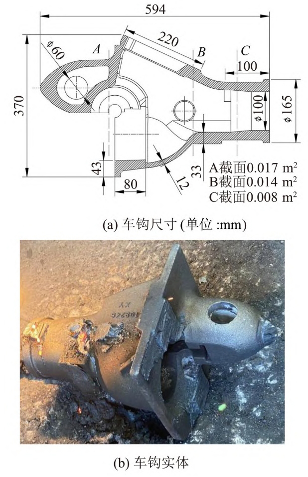
The coupler is made of investment casting and made of E-grade steel ZG25MnCrNiMo. The external contour dimensions are 594mm x 370mm x 350mm, belonging to large and complex investment castings. The minimum cross-sectional area of the longitudinal axis cross-section of the investment casting locomotive hook is 0.008m ^ 2, and its geometric model and physical object are shown in Figure 1.
Samples were taken from the as cast and heat treated state (normalized+910 ℃ quenching+2h590 ℃ tempering) of the coupler castings, and the microstructure was observed under optical microscopy (OM) and scanning electron microscopy (SEM). The results are shown in Figure 2.
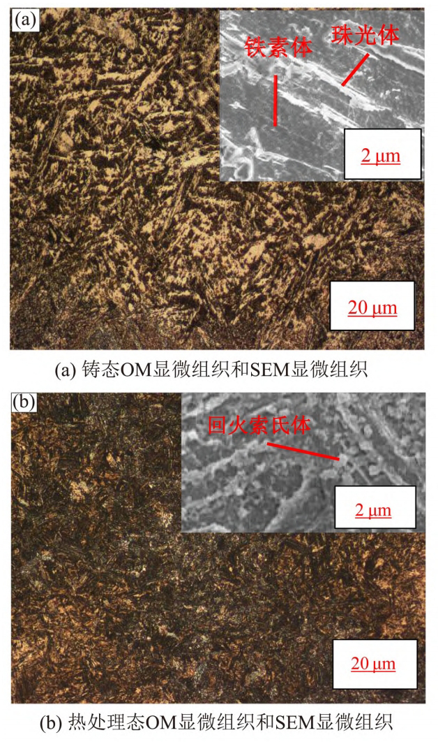
As shown in Figure 2 (a), the microstructure of investment cast locomotive hooks in the as cast state is mainly composed of pearlite and ferrite. Compared with the first level standard in TB/T2942.2-2018 “Steel Castings for Locomotives and Rolling Stock Part 2: Metallographic Structure Inspection Atlas”, the size and distribution morphology of the as cast grains exceed the standard requirements. After normalizing, preparing for heat treatment, and quenching and tempering treatment, the structure of the coupler casting is small and uniform tempered martensite, as shown in Figure 2 (b). Under high-power SEM observation, many small and uniform carbide particles are distributed on the ferrite matrix. Six specimens were cut from the large plane area of the coupler casting before and after heat treatment for tensile testing. The average value of the obtained data is shown in Table 1.
| Material | Elongation after fracture δ /% | Reduction of area ψ/% | Tensile strength σ B/MPa | Yield strength σ S/MPa | Elastic modulus E/MPa | Hardness/HBW |
| Before heat treatment | 2.1 | 3.9 | 626 | — | 78 220 | 235-241 |
| After heat treatment | 14.5 | 34.5 | 1 020 | 920 | 215 470 | 315-320 |
| Industry standard (after heat treatment) | ≥ 14 | ≥ 30 | ≥ 830 | ≥ 690 | 174 000 | 241-311 |
The tensile test results show that the tensile strength of the casting in the as cast state is between 550-675MPa, and its elongation is between 1.5% and 2 7%; After quenching and tempering treatment, its tensile strength reaches 900~1450MPa, yield strength is 920MPa, and elongation rate reaches up to 14.5%, which is significantly improved compared to the cast state. This is mainly because the heat treatment of normalizing and quenching effectively refines the grain size, improves defects such as inclusions and segregation. Compared with the main mechanical performance parameters of ZG25MnCrNiMo steel in the railway industry standard TB/T2942-2015 (after heat treatment), the heat treated investment casting locomotive couplers in this study meet the requirements for use.
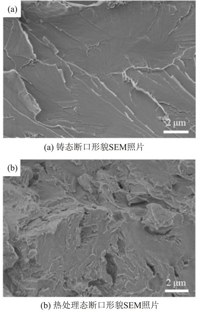
Electron microscopy observation of the tensile fracture surface revealed that there was no significant necking in the as cast specimen, and the cleavage surface of the cross-section was obvious, indicating brittle fracture. The microstructure of the fracture surface is shown in Figure 3 (a); After quenching and tempering, the fracture surface of the sample exhibits quasi cleavage fracture characteristics, as shown in Figure 3 (b). The ductile fracture surface shows discontinuous expansion, with many tearing edges on the quasi cleavage small section. The fracture behavior is between cleavage fracture and ductile fracture, and the toughness is significantly improved compared to as cast fracture.
2. Working principle and finite element model of investment casting locomotive coupler
2.1 Simulation method for fatigue life
During the life cycle of a component, fatigue life refers to the time it takes for crack initiation and propagation until fracture. Under the action of alternating loads, the initiation or propagation of cracks gradually forms. After multiple cyclic loading, the damage to the structure accumulates to a certain extent, causing the structure to lose its function. At present, there are two main methods for predicting fatigue life: stress life method and strain life method. The stress life method is based on the stress cycle number (S-N) curve, which describes the fatigue cycle number corresponding to the stress amplitude. This method is only applicable to high cycle fatigue (10 ^ 4 times or more), and its results are conservative. It may also predict fatigue failure for structures that do not actually experience fatigue. The strain life method is based on the strain cycle number (E-N) curve, which describes the fatigue cycle number corresponding to the strain amplitude. It is not limited to high cycle fatigue, has high accuracy, and the calculation speed during simulation is slower than stress fatigue. Choose the E-N method for simulation.
2.2 Connection and stress of investment casting locomotive couplers
When the locomotive coupler is coupled in investment casting, the hook head of one side of the coupler is inserted into the hook head hole of the other side of the coupler, as shown in Figure 4 (a). At this point, the inner surface of the convex cone presses the opposite hook tongue to rotate as it moves forward, causing the spring of the uncoupling cylinder to be compressed, and the hook tongue rotates 40 ° counterclockwise. When the connecting surface of the investment casting locomotive hook comes into contact, the inner side of the convex cone no longer compresses the other hook tongue. At this time, due to the action of the spring, the hook tongue rotates clockwise to return to its original state, which is in the locked position.
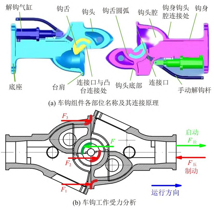
The investment casting locomotive hook is mainly used to connect the carriages, so the direction of force is longitudinal. The main part for transmitting force between investment casting locomotive hooks is the hook tongue. When the train starts, the investment casting locomotive hook is mainly subjected to tensile force. At this time, the arc surface of the hook tongue in the investment casting locomotive hook assembly is mainly subjected to force; When the train brake coupler is subjected to compression force, the main force in the investment casting locomotive coupler assembly is the hook tongue circular arc surface and the connection port position, ignoring gravity. The force during the operation of the investment casting locomotive coupler is shown in Figure 4 (b).
2.3 Finite Element Model of Investment Casting Locomotive Coupler Work
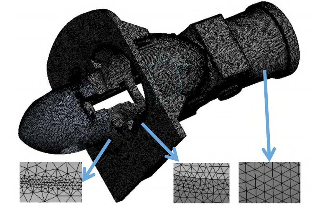
Due to the complex structure and uneven wall thickness of investment casting locomotive hooks, tetrahedral elements are used to divide investment casting locomotive hooks. In order to obtain more accurate calculation results, the global grid division starts from 10mm and gradually reduces the size of the division grid for calculation until the stress result changes less than 3%, and the location of stress concentration in the investment casting locomotive hook is determined. At this time, the global grid size of the investment casting locomotive hook has been reduced to 1.75mm. Then, local mesh refinement is performed on the stress concentration location, with a minimum mesh size of 0.5mm, as shown in Figure 5. The total number of nodes in the divided assembly model is 3369299, with 1924534 units.
2.4 Load capacity of investment casting locomotive couplers
The investment casting locomotive hook is subjected to the maximum tensile and compressive loads during start-up and braking. When the train starts, the investment casting locomotive hook is subjected to a tensile load, and the tensile force instantly reaches its maximum value, then gradually decays; When the train starts running smoothly, the tensile force tends to stabilize; When the train brakes, the investment casting locomotive coupler is subjected to a compressive load, and the compressive force instantly reaches its maximum, then gradually decays until the train stops and decays to zero. According to the Technical Specification for Subway Vehicle Couplers, the investment casting locomotive coupler and coupler seat should meet a static pressure of not less than 1000kN and a tensile force of not less than 800kN. The maximum tensile force when the vehicle runs smoothly is 600kN. Therefore, the static simulation analysis adopts the above load data, with the aim of examining whether the strength of the investment casting locomotive coupler meets the design requirements through the simulation analysis of the ultimate working load.
The fatigue analysis selected the 8-level load spectrum compiled from the measured load time history of the Daqin Line locomotive hook as the working condition loading of the investment casting locomotive hook. However, due to the fact that the Shibata style close contact investment casting locomotive coupler is used for urban rail passenger lines and differs from the maximum load of freight trains on the Daqin Line, the maximum load amplitude of the Daqin Line has been corrected, that is, all amplitudes exceeding 800kN are taken as 800kN. The fatigue simulation load spectrum of the Daqin Line is shown by the pink line in Figure 6.
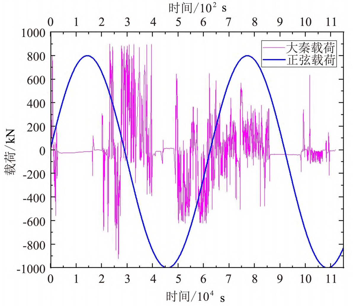
The Daqin Line is a freight transportation route with complex road conditions. Compared to rail vehicles operating in cities, the damage caused by operating loads on the Daqin Line is greater. To make the simulation results practical and comparative, fatigue analysis will be conducted using the busiest subway line 3 in Chongqing as an example. In the operation of rail transit, there are mainly three stages between two stations: start-up acceleration, uniform and stable operation, and braking deceleration. Therefore, the load spectrum can be simplified as a blue sine waveform load in Figure 6 for simulation calculation, with an amplitude of 800kN required by the technical specifications for subway couplers.
3. Simulation Results and Discussion on the Mechanical Performance of Locomotive Couplers in Investment Casting
3.1 Static strength simulation analysis
The investment casting locomotive coupler bears tensile and compressive loads of 600kN, 800kN, and 1000kN, respectively. The stress distribution of the investment casting locomotive coupler under stable operating conditions, starting conditions, and emergency braking conditions is shown in Figure 7 (a), (b), and (c). From the simulation results analysis, it can be seen that under a stable operating condition of 600kN static tensile load, the maximum stress at the traction end of the coupler is 362.04MPa, and the maximum deformation at the traction end is 2.41mm; Under the starting condition, the maximum stress on the investment casting locomotive hook is 482.72MPa, and the maximum deformation is 3.21mm. The larger value occurs at the bottom of the hook head. From the force analysis of the coupler in Figure 4 (b), it can be seen that when the coupler is under tension, the force position is mainly on the circular arc surface of the coupler tongue, as shown in the green circular arc in Figure 4 (b), which is not at the center position of the coupler head, resulting in uneven force distribution on the coupler head and maximum stress at the bottom of the coupler head. From the simulation results, it can be seen that the position of maximum stress is consistent with the position of stress concentration, as shown in Figure 7 (a) and (b). According to the mechanical test results of investment casting locomotive hook material (see Table 1), it can be seen that the average tensile limit of investment casting locomotive hook material after heat treatment is 1020MPa, and the stress under normal working conditions is much lower than the yield limit of the material. The elongation after fracture of the coupler material after heat treatment is 14.5%. The total length of the investment casting locomotive coupler after removing the hook head is 430mm, and the maximum deformation of the coupler can be calculated to be 62 35mm, according to the simulation results in Figure 7 (d) (e), the total deformation of the investment casting locomotive coupler under the starting condition is 3.21mm, and the maximum total deformation during smooth operation is 2.41mm, which is far from reaching the maximum variable deformation. Therefore, the investment casting locomotive coupler can be safely used under normal working conditions.
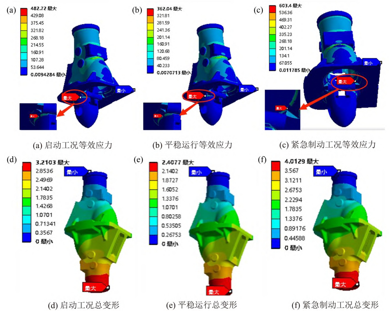
The train has a huge momentum during operation, and emergency braking requires a braking force of 1.5 times that of conventional braking, which is 1000 kN. From the analysis results, it can be seen that under emergency braking conditions, the maximum stress on the investment casting locomotive hook is 603.4MPa, and the maximum deformation is 4.01mm. The location of the maximum stress is near the connection port and the hook tongue protrusion, as shown in Figure 7 (f). From the analysis of the compression force on the locomotive hook in investment casting, it can be seen that the main points are the connecting port and the hook tongue circular arc surface, as shown in the red arc in Figure 4 (b). Due to the complex shape of the connecting port and the hook tongue convex platform, stress concentration may occur, which is consistent with the results of simulation analysis, as shown in Figure 7 (c). Meanwhile, based on the analysis of simulation results and mechanical test results, the investment casting locomotive coupler can be safely used under this compressive load.
3.2 Methods and Results Discussion of Coupler Fatigue Analysis
3.2.1 Fatigue analysis methods
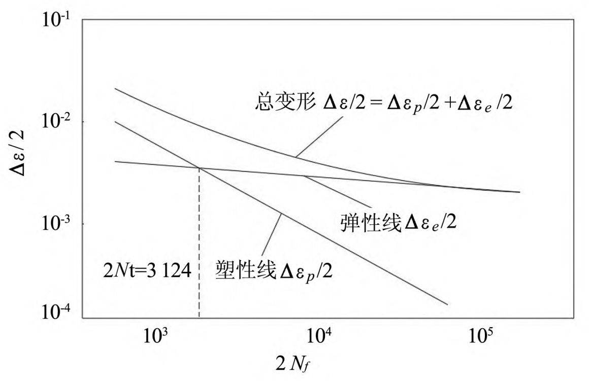
Fatigue simulation mainly studies the structural damage of investment casting locomotive couplers under tension compression cyclic stress. The main method is to estimate the fatigue life of investment casting locomotive couplers based on the amount of damage suffered by investment casting locomotive couplers in one stress cycle. Maintain the total strain amplitude value during fatigue testing Δε / 2 unchanged, test each specimen with different strain amplitudes until the specimen fails, record the fatigue life Nf of each test, and calculate the strain amplitude ε A= Δε / Draw log in logarithmic coordinates with 2Nf as the x-axis and 2 as the y-axis( Δε / 2) The – log (2Nf) curve yields the strain fatigue life curve. The double logarithmic curve of strain fatigue life of E-grade cast steel coupler material is shown in Figure 8.
According to fatigue theory, the relationship between stress and fatigue life is expressed as the formula:
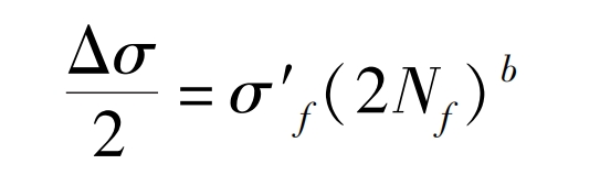
In the formula: b is the fatigue strength index; σ′ F is the fatigue strength coefficient.
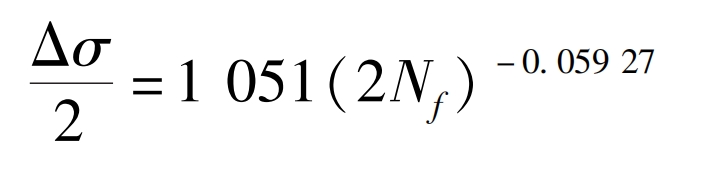
The fatigue strength index b of E-grade steel coupler material is -0 05927, fatigue strength coefficient is σ′ F is 1051.
Integrate the fatigue strength index b with the fatigue strength coefficient σ′ Substitute the f data into equation (1) to obtain the investment casting locomotive hook material Δσ/ 2-2 Nf relationship (2):
The relationship between plastic strain and fatigue life is equation (3):
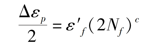
In the formula: ε′ F is the fatigue ductility coefficient; C is the fatigue ductility index.
The fatigue ductility index c of E-grade cast steel coupler material is -1.03023, and the fatigue ductility coefficient is -1.03023 ε′ F is 13.2987.
Based on the analysis of strain fatigue test results by Manson and Coffin, the strain fatigue life formula (4) is derived:
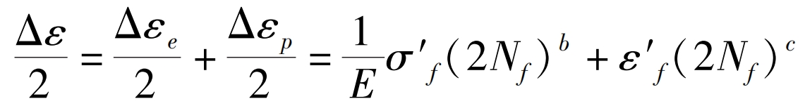
Add b σ′ f. C ε′ Substitute the f data into equation (4) to obtain the Manson Coffin equation (5) for E-grade cast steel:
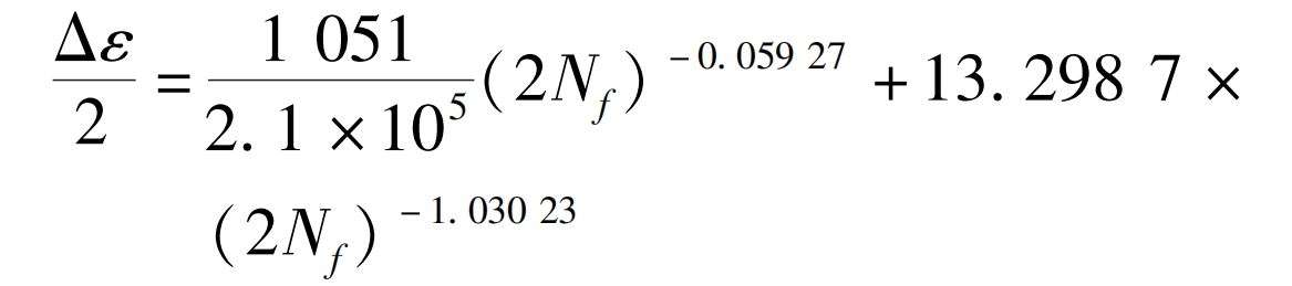
By substituting the damage caused by one stress cycle into equation (5), the fatigue life of investment casting locomotive couplers can be analyzed and estimated.
3.2.2 Fatigue simulation results and discussion
Import the mechanical data obtained from material testing and static strength simulation results into the ANSYS code module, and set the surface of the hook tongue as the casting surface (-40) in fatigue analysis μ M < Ra ≤ 75 μ m) The surface quality is close to the actual investment casting of locomotive couplers, which will make the fatigue calculation results more conservative and safe.
1) Fatigue simulation analysis of load spectrum on the Daqin Line
Import the measured load spectrum data of the Daqin Line, and use the strain life (E-N) curve to perform BrownMiller multi axis fatigue analysis and Goodman average stress correction. The ncode module calculates the number of fatigue cycles in the load spectrum of investment casting locomotive couplers, as shown in Figure 9. As shown in Figure 9, the most fatigued position of the investment casting locomotive hook appears at the selected position in Figure 9, with a minimum fatigue life of 105.2 times.
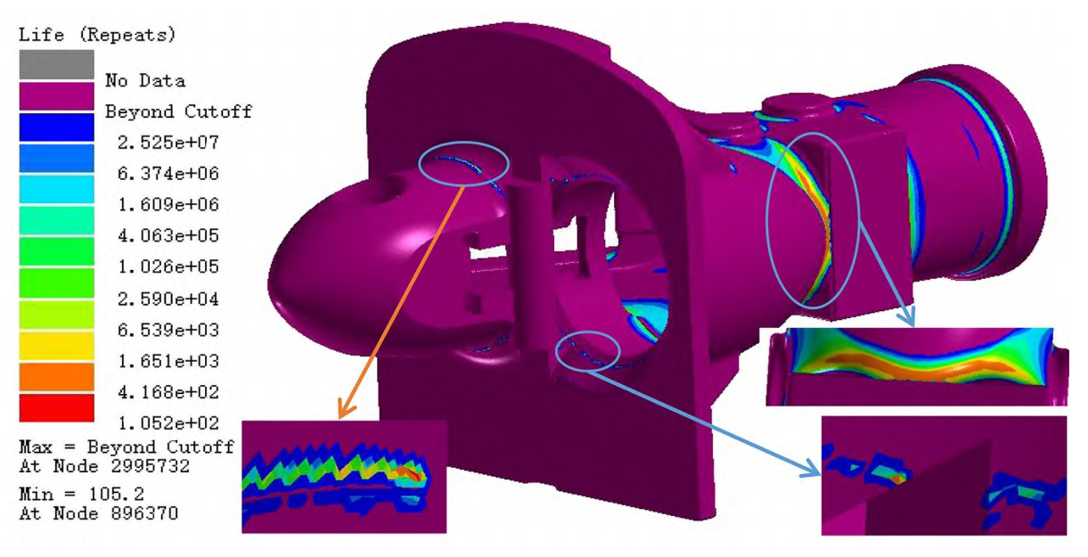
Comparing the stress cloud map of the static stress analysis results in Figure 7 with the locations prone to fatigue, it can be seen that the locations prone to fatigue are consistent with the stress concentration locations in the static stress simulation in the previous text. These positions are mainly the bottom of the investment casting locomotive hook head, the connection port, and the connection of the hook body hook head cavity. Therefore, these positions need to be taken seriously in the design and processing stages, and should also be monitored in daily maintenance.
The load spectrum of the loaded Daqin Line has a total length of 15000km, and the simulation results show that the life of the investment casting locomotive hook under the worst alternating load is 105.2 cycle loads. The life data is substituted into equation (6):
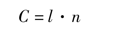
In the formula: C represents the total safe driving distance; L is the total length of the load spectrum; N is the number of cycles for investment casting locomotive hooks. Then C=1578000km is calculated.
2) Fatigue simulation analysis of Chongqing Metro Line 3
Close fitting investment casting locomotive couplers are commonly used in high-speed trains, urban subways, and light rail vehicles. The total length of Chongqing Metro Line 3 is 56.4km, and trains run 6 times a day. If the mileage that can be safely operated by investment casting locomotive hooks on the Daqin Line is simply converted to Chongqing Metro Line 3 for comparison, the data can be substituted into equation (7):
The calculated operational life of investment casting locomotive couplers on Chongqing Metro Line 3 is 12.8 years. Of course, using the actual load spectrum of the Daqin Line with complex road conditions to estimate the smooth operation life on urban rail is inaccurate. The working conditions between the two stations of urban rail mainly include starting acceleration, constant speed driving, and braking deceleration, so a sine wave can be used as the load spectrum for life assessment. In addition, as an important connecting and safety component of locomotives, investment casting locomotive couplers need to consider overload situations. Therefore, the load amplitude of 800kN for investment casting locomotive couplers, as well as various overload loads of different sizes such as no-load, half load, and other loads, are taken as conditions. At the same time, the maximum internal stress inside the investment casting locomotive couplers under different loads is calculated through static simulation, and the fatigue life curve of investment casting locomotive couplers is drawn, The result is shown in Figure 10.
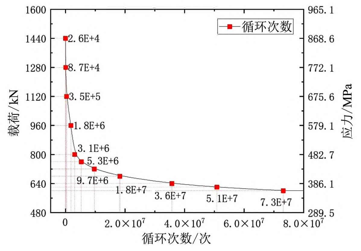
As shown in Figure 10, the fatigue life of investment casting locomotive couplers decreases with the decrease of load (or the maximum internal stress inside the coupler). When the investment casting locomotive coupler operates at a load of 1440kN all year round, the maximum tensile stress inside the investment casting locomotive coupler is as high as 868 At 6MPa, the coupler can only withstand 2.6 × 10 ^ 4 sine loads, which theoretically can safely operate for 0.26 years. When the investment casting locomotive coupler works normally with a load of 600kN, it can withstand 5.1 × 10 ^ 7 sinusoidal load impacts. When the load of investment casting locomotive couplers is reduced to 580kN, the maximum stress inside the investment casting locomotive couplers is 349.86MPa, and the fatigue life curve of the couplers becomes horizontal, which means that theoretically, investment casting locomotive couplers will not experience fatigue. According to convention, the fatigue test cycle base requirement for general steel materials is 10 ^ 7 levels, so the ability of investment casting locomotive couplers to withstand 5.1 x 10 ^ 7 sinusoidal load impacts during normal operation fully meets the usage requirements.
In addition, the symmetric cyclic fatigue strength value of steel materials σ - 1 is generally about its tensile strength value σ About 1/2 of b, while pulse fatigue strength σ 0 is generally lower than symmetric fatigue strength. The average tensile limit of the investment casting locomotive hook material is 1020MPa (see Table 1). According to the fatigue life curve in Figure 10, it can be seen that when the investment casting locomotive hook is loaded with a sine wave load of 800kN amplitude, the maximum internal stress inside the investment casting locomotive hook is 482.7MPa, which means the fatigue strength under this load is 482.7MPa. When the investment casting locomotive coupler is loaded with sine wave loads of 680, 640, 620, and 600kN amplitudes, its fatigue life reaches 1.8 x 10 ^ 7, 3.6 x 10 ^ 7, 5.1 x 10 ^ 7, and 7.3 x 10 ^ 7 cycles, respectively. This group of fatigue lives obviously meets the requirement of reaching the base 10 ^ 7 level of steel fatigue cycles, At this point, the corresponding fatigue strength values are 410.2 MPa, 386.1 MPa, 373.9 MPa, and 361.9 MPa, which are lower than the theoretical symmetric cyclic fatigue strength of investment casting locomotive couplers, which is about 510 MPa. This also indicates that the results of fatigue life simulation are reliable.
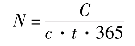
There are a total of 45 stations on Chongqing Line 3, with each train running 6 times a day. Substitute the number of cycles of investment casting locomotive couplers under different loads in Figure 10 into equation (8):
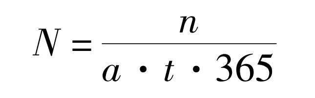
In the formula, N represents the service life of investment casting locomotive couplers; N is the minimum number of cycles for investment casting locomotive couplers; T is the number of runs per day; A is the number of stations.
It can be estimated that the service life of investment casting locomotive couplers under sinusoidal loads of 800kN and 600kN amplitudes is 31.5 years and 740.7 years, respectively. According to the Technical Specification for Subway Vehicle Couplers, the service life of investment casting locomotive couplers should not be less than 30 years. After heat treatment, the service life of investment casting locomotive couplers far exceeds the requirements in the specification. However, if the train frequently experiences overload, timely maintenance should be carried out.
4. Conclusion
1) Under scanning electron microscopy, it was observed that the investment casting material for car hooks has a uniform structure, small grains, and no obvious casting structural defects; The tensile test shows that the maximum tensile strength in the cast state can reach 675MPa, and the maximum tensile strength after heat treatment can reach 1540MPa. The evaluation can reach 1020MPa, and the microstructure and properties meet the requirements of investment casting locomotive couplers.
2) The stress and deformation of the investment casting locomotive hook are far less than the allowable yield strength and deformation of the hook under three working conditions of starting, smooth operation, and emergency braking. The investment casting locomotive hook meets the service requirements.
3) The sine load fatigue life curve of investment casting locomotive coupler was drawn through simulation. The fatigue life of the coupler loaded with the load spectrum of the Daqin Line can reach up to 12.8 years, while the fatigue life of the Chongqing Rail Line 3 in the 800kN amplitude sine spectrum is 31.5 years. The investment casting locomotive coupler meets the requirements for use, and the simulation results can provide a basis for the maintenance of investment casting locomotive couplers.