
In my extensive experience surveying marine equipment, the production of ship anchors, typically achieved through manual sand mold casting, presents significant and persistent challenges. The process heavily relies on production experience and on-site trials to address casting defects, resulting in suboptimal production efficiency. As vessel tonnage increases, so does the size and weight of anchors. Existing casting methodologies often fail to achieve directional solidification, leading to defects such as shrinkage cavities and porosity within the anchor crown and its flanks, as well as cracks at the transition zones between the crown and the flukes. These issues result in poor-quality castings with excessive residual stress, causing substantial economic losses for both manufacturers and ship operators. This article, based on my first-hand inspections, analyzes the common defects found in large steel casting anchors and proposes targeted control measures for critical production nodes.
The manufacturing process for a steel casting anchor encompasses several key stages: casting process design, pattern making, sand mixing, molding, mold assembly, melting, pouring, shakeout and cleaning, removal of gates and risers, defect repair, heat treatment, relevant testing, and surface finishing. From my perspective, controlling the following nodes is paramount for quality.
Critical Nodes in Steel Casting Anchor Production
1. Casting Process Design
A meticulous casting process design is the fundamental guarantee for achieving high-quality castings, particularly sound internal quality. In my practice, I emphasize several aspects:
(1) Determination of Pouring Position: This requires comprehensive consideration of the steel alloy type, structural configuration, and technical specifications. The goal is to position critical machined surfaces, high-stress areas, and regions prone to defects optimally. For instance, thick sections are susceptible to shrinkage porosity, cavities, and hot tears; large planar surfaces at the bottom of the anchor crown are prone to sand inclusions, scabs, and distortion; thin-walled areas like the flukes risk mistruns, cold shuts, and cold cracks; and transition zones between thick and thin walls are likely locations for hot tears.
(2) Determination of Process Parameters: Parameters including dimensional and weight tolerances, machining allowances, linear shrinkage rates, and compensation for distortion must be carefully selected. These should be determined conservatively, based on the foundry’s specific capabilities.
(strong>) Riser Design: Casting is a process of continuous heat extraction by the mold, leading to air gap formation, and simultaneous solidification of the metal, resulting in volumetric contraction. Risers are primarily used to compensate for this solidification shrinkage, thereby preventing shrinkage cavities and porosity. They also serve secondary functions like venting, slag trapping, and indicating mold fill. Therefore, risers must be sufficient in number and size, typically placed at the heaviest sections of the steel casting.
(4) Gating System Design: Pouring is usually done with a bottom-pour ladle. The gating system consists of the pouring cup, sprue, runners, and ingates. Given that cast steel has a high melting point, poor fluidity, high shrinkage, and is prone to oxidation, the gating system should be simple, with large cross-sectional areas, robust to withstand impact, and designed to fill the mold quickly and smoothly. The metal stream should not be overly dispersed, and the system must facilitate directional solidification towards the risers.
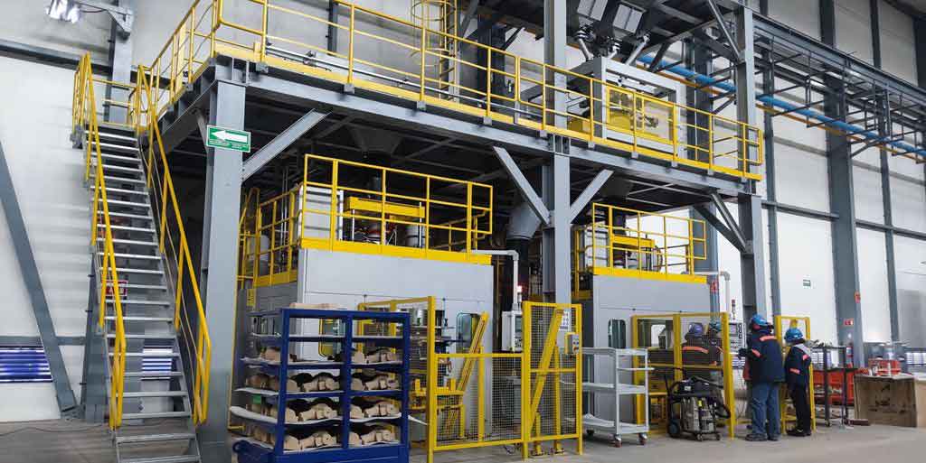
2. Molding and Core Sand
Molding and core sand generally comprises base sand, binders, and additives. For marine steel castings with pouring temperatures around 1560°C, the base sand must possess high refractoriness (SiO2 content ≥ 97%), good chemical stability, and high permeability (coarse, preferably rounded grains) to avoid defects like gas holes, sand inclusions, and metal penetration. Key properties to monitor are sand strength, permeability, and moisture content.
3. Melting and Pouring
Common melting equipment for steel casting includes electric arc furnaces and induction furnaces. Taking the oxidizing arc furnace process as an example, I focus on:
(1) Chemical Composition Control: Primarily controlling C, P, S, Si, and Mn levels.
(2) Temperature Control: Critical temperatures are the metal temperature at the end of the oxidation period (ensuring effective deoxidation and desulfurization in the reduction period) and the tap temperature (ensuring proper fluidity for casting completion).
(strong>) Slag Control: Effective control during the reduction period for deoxidation and desulfurization. A well-formed white slag, typically indicated by an FeO content below 0.8% to 1.0%, is a good marker (used when final carbon content is < 0.35%).
(4) Deoxidation Quality: The degree of deoxidation at the end of the reduction period under white slag must be verified, often using a cup test sample.
(5) Pouring Practice: Using a bottom-pour ladle allows inclusions and gases to float up, preventing them from entering the mold. Precise control of pouring temperature and speed is essential.
| Process Node | Key Control Parameters | Typical Target/Standard | Purpose |
|---|---|---|---|
| Melting | C, P, S Content; Tap Temperature | Per grade spec.; ~1600°C | Achieve desired chemistry & fluidity |
| Molding Sand | SiO2 Content, Permeability, Moisture | >97%, >100, 3.5-4.5% | Prevent sand-related defects |
| Pouring | Pouring Temperature, Speed | 1550-1580°C, Controlled rate | Ensure complete fill, minimize turbulence |
| Riser Design | Riser Volume, Feeding Distance | V_riser ≈ η * V_shrinkage | Compensate for solidification shrinkage |
| Shakeout | Shakeout Temperature | 300 – 500°C | Minimize thermal stress & distortion |
4. Shakeout and Cleaning
After pouring, the casting must cool in the mold. Premature shakeout at high temperatures exposes the red-hot steel casting to rapid air cooling, inducing distortion and cracking. Excessively low shakeout temperatures hinder cleaning and prolong cycle times. An optimal shakeout temperature ranges from 300°C to 500°C. Cleaning involves removing gates, risers, flash, fins, and any residual sand or core material.
Analysis of Typical Defects in Steel Casting Anchors
A pertinent case study involves the inspection of an 18-ton high-holding-power (HHP) anchor for a very large vessel. HHP anchors, characterized by large, long flukes and a broad crown, offer superior holding power and stability.
1. Defect Discovery
After successfully passing standard weight, drop, hammer, and proof load tests, magnetic particle inspection (MT) was conducted. The inspection revealed indications of suspected cracks in the high-stress region at the root of the flukes—the transition zone between the crown and the fluke. The orientation of these indications aligned with the principal stress direction, constituting a critical defect that could lead to fluke fracture in service. Upon rigorous grinding of the indicated areas for verification, significant hot cracks beneath the surface were confirmed.
2. Root Cause Analysis
The consistent location of cracks across multiple anchors in the batch pointed decisively to a flaw in the steel casting process. The crack morphology—wide and torn—identified them as hot tears. This transition zone features an abrupt change in section thickness, from the massive crown to the relatively thinner fluke. During solidification, the thinner fluke cools and gains strength rapidly, while the thicker crown section at the junction cools much slower. The contraction of the slower-cooling, mushy zone is constrained by the already solid, stronger thinner section, generating tensile stresses that exceed the hot strength of the material at that point, resulting in a hot tear. This can be conceptualized by considering the thermal stress ($\sigma_{thermal}$) developed:
$$\sigma_{thermal} = E \cdot \alpha \cdot \Delta T$$
Where $E$ is Young’s modulus, $\alpha$ is the coefficient of thermal expansion, and $\Delta T$ is the temperature difference between the constrained sections. In zones of abrupt thickness change, $\Delta T$ is significant, leading to high stress.
The solidification time ($t_s$) for a simple shape can be approximated by Chvorinov’s rule:
$$t_s = k \cdot \left( \frac{V}{A} \right)^n$$
where $V$ is volume, $A$ is surface area, and $k$ and $n$ are constants. The large $V/A$ ratio of the crown leads to a much longer $t_s$ compared to the fluke, creating the condition for differential contraction.
3. Defect Repair Protocol
For such critical cracks, the approved repair procedure involves: 1) Complete removal of the defect by grinding/chiseling to sound metal. 2) Welding repair using qualified procedures and welders, based on the final dimensions of the prepared cavity. 3) Immediate post-weld heat treatment (PWHT), typically a full stress-relief anneal, performed on the entire steel casting to eliminate welding stresses. 4) Non-destructive testing (NDT) re-inspection no less than 48 hours after PWHT to verify repair integrity.
4. Corrective and Preventive Measures
The core issue is excessive internal stress due to drastic section changes. Therefore, any measure that reduces this stress or mitigates its effects can prevent crack initiation. Effective countermeasures implemented included:
(1) Structural Optimization: Redesigning the fluke root geometry to create a more gradual transition between thick and thin sections, reducing the severity of the thermal hotspot and the associated casting stress.
(2) Enhanced Feeding & Controlled Solidification: Optimizing riser size and placement, and strategically using chill plates to promote more favorable solidification sequencing, thereby reducing internal stresses.
(strong>) Controlled Cooling: Extending the in-mold cooling (hold) time before shakeout to allow for more uniform temperature reduction and stress relaxation within the steel casting.
Adopting these measures in subsequent production runs led to a marked reduction in crack defects, significantly improving the quality of these large steel castings.
| Defect Type | Typical Location | Root Cause | Preventive Strategy in Steel Casting |
|---|---|---|---|
| Hot Tear/Crack | Thick-thin transition (Crown/Fluke) | High thermal stress from differential contraction | Gradual section changes, chills, optimized risers, delayed shakeout. |
| Shrinkage Cavity/Porosity | Heavy sections (Crown center) | Insufficient feed metal during solidification | Adequate riser volume/size, proper gating for directional solidification. |
| Cold Shut / Mistrun | Thin sections (Fluke tips) | Low metal fluidity, slow pour, low temp | Increase pouring temp/speed, optimize gating for thin sections. |
| Sand Inclusion / Scab | Large flat surfaces | Mold surface instability, erosion | Increase sand strength/refractoriness, use mold coatings, stable pouring. |
| Gas Porosity | Random, subsurface | High sand moisture, poor deoxidation | Control sand moisture, improve melting/deoxidation practice, dry ladles. |
Holistic Quality Control Framework for Steel Casting
Beyond addressing specific defects, a robust quality assurance system is vital for consistent production of reliable large steel castings like anchors. This involves:
Process Modeling & Simulation: Modern computational tools can simulate mold filling, solidification, and stress development. Running simulations before creating patterns allows for virtual optimization of riser and gating design, significantly de-risking the steel casting process for new, large geometries.
Non-Destructive Evaluation (NDE): A multi-method NDE approach is crucial:
- Magnetic Particle Testing (MT): Excellent for surface-breaking defects in ferromagnetic materials like cast steel.
- Ultrasonic Testing (UT): Essential for detecting subsurface defects like shrinkage porosity, inclusions, and internal cracks. The depth and size of flaws can be estimated.
- Radiographic Testing (RT): Provides a 2D image of internal integrity, very effective for volumetric defects but with safety and access considerations.
The choice and sequence of NDE methods depend on the criticality of the casting section and the type of defect most likely to occur.
Metallurgical and Mechanical Verification: This includes chemical analysis from a separately cast coupon, tensile and impact tests to verify mechanical properties meet specification, and macro/micro-examination to check for soundness and microstructure.
The production of large marine anchors via steel casting is a complex metallurgical and engineering challenge. Success hinges on a deep understanding of solidification principles and rigorous control at every node—from the initial design and simulation, through meticulous mold and melt preparation, to controlled pouring and cooling. The case of hot tears at the crown-fluke junction underscores how geometric factors drive thermal stresses. Implementing corrective measures like profile optimization, improved feeding, and controlled cooling is proven to enhance quality. Ultimately, marrying sound steel casting engineering with a comprehensive quality management system, incorporating advanced simulation and stringent NDE, is the pathway to manufacturing the highly reliable anchors required by modern shipping. The entire endeavor of steel casting for such critical components demands nothing less than this integrated, vigilant approach.