
In my experience working with advanced foundry technologies, the lost foam casting process has always been a fascinating area due to its ability to produce complex geometries with minimal post-processing. This process, which involves using expandable polystyrene patterns surrounded by unbonded sand, relies heavily on precise vibration to ensure proper compaction and prevent defects. Over the years, I have observed that the evolution of the lost foam casting process has been rapid, with production line equipment becoming increasingly sophisticated. However, when our facility transitioned from a gray iron lost foam casting process to an aluminum alloy lost foam casting process, we faced significant challenges related to pattern deformation and penetration defects, leading to scrap rates as high as 18%. This prompted a deep investigation into our vibration table and flask system, culminating in a redesign that drastically improved outcomes. In this article, I will detail the problems we encountered, the analytical approaches we used, and the innovative solutions we implemented, all centered around optimizing the lost foam casting process.
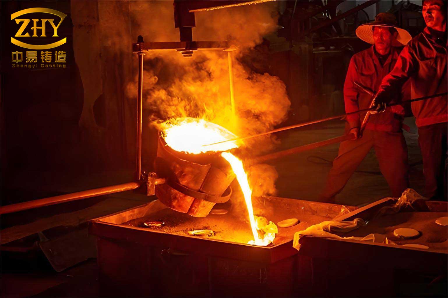
The lost foam casting process is inherently dependent on the uniformity of sand compaction around the foam pattern. Any inconsistency can lead to distortions, metal penetration, or poor surface finish. In our initial setup, we utilized a vibration table from a renowned manufacturer, specifically a HDCT model, paired with square flasks measuring 800mm × 800mm × 1200mm internally. The flask design included a bottom vacuum chamber 120mm deep, which was adequate for the gray iron lost foam casting process where the coating had higher strength. However, upon switching to the aluminum alloy lost foam casting process, the coating thickness was reduced and its strength lowered to meet permeability requirements without vacuum assistance. This change exposed critical flaws in our vibration system. The vibration table, operating with eccentric blocks set at 40% and frequencies between 1000 to 1500 rpm, caused excessive flask hopping, systematic pattern tilting, and sand shifting eastward. The upper part of the flask exhibited excessive amplitude, resulting in poor sand compactness. Adjusting the eccentric blocks above 40% worsened the hopping, while settings below 40% reduced the excitation force, compromising compactness and efficiency. This directly impacted the lost foam casting process, elevating deformation-related scrap rates to unprecedented levels.
To systematically address these issues, I led an analysis focusing on the dynamics of the vibration table and flask interaction. The original vibration table had a square platform with three support pillars arranged in an isosceles triangle, where the eastern pillar served as the apex. The center of the upward excitation force was aligned with the centroid of this triangle, which was offset by 100mm from the platform’s geometric center. Meanwhile, the square flask had its centroid aligned with the platform’s center, but the three conical flanges at its bottom rested on the vibration table’s pillars. This misalignment meant that the excitation force and the gravitational reaction force were not collinear, creating an imbalance that led to uneven sand compaction. The force distribution can be described using the following formula for the net moment generated:
$$ M = F_e \times d $$
where \( M \) is the moment causing tilting, \( F_e \) is the excitation force, and \( d \) is the offset distance between the force center and the flask’s centroid. In our case, this moment contributed to the pattern倾倒 and sand displacement. Additionally, the excitation force transmitted through the flask walls was inefficient because the support pillars did not contact the sidewalls directly. The flask’s bottom, made of 8mm steel plate for the vacuum chamber, had low rigidity, further dampening the vibration energy. The transmission efficiency \( \eta \) of vibration through a structure can be modeled as:
$$ \eta = \frac{E_{output}}{E_{input}} = e^{-\beta L} $$
where \( \beta \) is a damping coefficient dependent on material and geometry, and \( L \) is the transmission path length. For hollow structures like our original flask bottom, \( \beta \) is higher, reducing \( \eta \). Moreover, the vibration amplitude increased with height due to the flask’s dynamics, described by the wave equation for a vertical beam:
$$ \frac{\partial^2 u}{\partial t^2} = c^2 \frac{\partial^2 u}{\partial z^2} $$
where \( u \) is the displacement, \( t \) is time, \( z \) is the vertical coordinate, and \( c \) is the wave speed. This led to loosening of already compacted sand at the top, making control difficult. We also discovered weight variations among our 150 flasks, with discrepancies exceeding 60 kg, affecting the vibration response since the excitation force \( F_e \) is given by:
$$ F_e = m_e e \omega^2 $$
Here, \( m_e \) is the eccentric mass, \( e \) is the eccentricity, and \( \omega \) is the angular frequency. With fixed \( F_e \), heavier flasks experienced lower acceleration, worsening inconsistency. The table below summarizes the key issues identified in the original lost foam casting process setup:
| Issue Category | Specific Problem | Impact on Lost Foam Casting Process |
|---|---|---|
| Force Alignment | Offset between excitation force center and flask centroid | Uneven sand compaction, pattern tilting |
| Flask Design | Square shape with three-point support on a triangle | Inherent imbalance in force distribution |
| Vibration Transmission | Hollow pillars and thin bottom plate | Reduced energy transfer to sand |
| Dynamic Response | Amplitude amplification with height | Poor compactness at top, sand loosening |
| Equipment Variability | Flask weight differences up to 60 kg | Inconsistent vibration across production line |
| Coating Change | Lower strength in aluminum lost foam casting process | Increased susceptibility to deformation |
Based on this analysis, we formulated a redesign strategy targeting both the vibration table and the flasks. For the vibration table, we reconfigured the three support pillars from an isosceles triangle to an equilateral triangle, with its centroid coinciding exactly with the platform’s center. This ensured that the excitation force vector passed through the flask’s centroid, minimizing moments. We also replaced the hollow pillars with solid steel rods to improve vibration transmission, as solid materials have a lower damping coefficient \( \beta \). The excitation force equation was recalibrated to account for this change, with the new force \( F_e’ \) being more efficient:
$$ F_e’ = \eta’ m_e e \omega^2 $$
where \( \eta’ \) is the improved transmission efficiency. For the flasks, we undertook a complete redesign. The square shape was abandoned in favor of a cylindrical design with an internal diameter of 800mm and a reduced height of 1000mm. This eliminated the vacuum chamber, and the bottom was replaced with a 25mm thick steel plate to enhance rigidity. The cylindrical geometry naturally distributes forces more evenly, which is crucial for the lost foam casting process. Three support flanges were positioned on the flask’s sidewall at 120-degree intervals, directly transmitting excitation forces to the sand via the sidewalls. This design ensures that each flange bears an equal share of the load, as described by the equilibrium condition:
$$ \sum_{i=1}^{3} F_i = 0 \quad \text{and} \quad \sum_{i=1}^{3} \mathbf{r}_i \times F_i = 0 $$
where \( F_i \) are the forces at each flange and \( \mathbf{r}_i \) are their position vectors. The reduced flask height mitigates amplitude amplification, as the wave equation solution shows lower displacement at the top for shorter lengths. We also implemented stricter manufacturing tolerances, ensuring that all 150 flasks had a weight variation within 10 kg, promoting consistency across the lost foam casting process line. The table below compares the key parameters before and after the redesign:
| Parameter | Original Design | Redesigned System | Benefit for Lost Foam Casting Process |
|---|---|---|---|
| Flask Shape | Square (800mm × 800mm × 1200mm) | Cylindrical (Ø800mm × 1000mm) | Even force distribution, reduced deformation |
| Bottom Structure | Vacuum chamber, 8mm steel | Solid 25mm steel plate | Improved vibration transmission, higher rigidity |
| Support Points | Three pillars in isosceles triangle | Three flanges in equilateral triangle on sidewall | Collinear force and reaction, balanced loading |
| Pillar Material | Hollow thick-walled pipe | Solid steel rod | Reduced damping, higher efficiency |
| Flask Weight Consistency | Variation > 60 kg | Variation < 10 kg | Uniform vibration response |
| Vibration Frequency Range | 1000–1500 rpm (with issues) | 1800–2000 rpm (stable) | Better sand compactness, shorter cycle time |
After implementing these changes, we conducted extensive trials to validate the improvements in the lost foam casting process. The redesigned vibration table was operated with eccentric blocks set at 40%, but we were able to increase the frequency to 1800–2000 rpm without inducing excessive hopping. The vibration became notably smoother, with minimal sand “wave” phenomena. We monitored the wear on the flask flanges and the vibration table’s nylon pads, observing uniform wear across all three contact points, indicating balanced force distribution. The deformation-related scrap rate, which had peaked at 18% in the aluminum lost foam casting process, dropped dramatically. Through iterative parameter optimization—adjusting sand addition rates, vibration duration, and frequency—we achieved a scrap rate as low as 1%, consistently maintaining it below 3%. This represents a monumental success for our lost foam casting process operations.
The mathematical modeling of the improved system further confirms these results. The vibration response of the flask can be approximated as a damped harmonic oscillator, with the equation of motion:
$$ m \ddot{x} + c \dot{x} + k x = F_e’ \sin(\omega t) $$
where \( m \) is the effective mass of the flask and sand, \( c \) is the damping coefficient, \( k \) is the stiffness, and \( x \) is the displacement. The steady-state solution shows a resonance frequency \( \omega_r = \sqrt{k/m} \), which we optimized by adjusting \( k \) through the flask’s rigid design and \( m \) via consistent weight. The sand compactness \( \rho \) as a function of vibration intensity \( I \) and time \( t \) can be expressed empirically:
$$ \rho(t) = \rho_0 + \alpha I t e^{-\gamma t} $$
where \( \rho_0 \) is the initial density, and \( \alpha, \gamma \) are constants. Our redesign increased \( I \) by improving force transmission, leading to faster and more uniform compaction. Additionally, the loss factor \( \tan \delta = c / (2 \sqrt{mk}) \) was reduced, minimizing energy dissipation. These technical enhancements directly benefit the lost foam casting process by ensuring that the foam pattern remains stable and the sand provides adequate support during pouring.
In conclusion, the lost foam casting process is a delicate balance of material science and mechanical engineering. Our journey from high scrap rates to optimal performance underscores the importance of holistic equipment design. By rethinking the vibration table and flask geometry, we aligned forces, enhanced vibration transmission, and standardized components. This not only solved the immediate problem of deformation in the aluminum lost foam casting process but also provided a scalable framework for future upgrades. The lost foam casting process continues to evolve, and I believe that such data-driven redesigns are key to unlocking its full potential. The integration of dynamic analysis, as shown through the formulas and tables here, offers a blueprint for others in the industry facing similar challenges. Ultimately, every aspect of the lost foam casting process—from pattern coating to vibration—must be harmonized to achieve defect-free castings, and our experience proves that even mature equipment can be reinvented for better outcomes.
Looking ahead, we plan to explore further optimizations, such as real-time monitoring of vibration parameters using sensors and adaptive control systems. This could lead to even tighter control over the lost foam casting process, reducing scrap rates toward zero. The principles we applied—force balance, efficient energy transfer, and consistency—are universal and can be adapted to other casting processes. As the lost foam casting process gains traction for lightweight alloys and complex parts, I am confident that our redesign will serve as a benchmark, driving innovation and efficiency in foundries worldwide. The lost foam casting process is not just a method; it’s a dynamic ecosystem where every component, no matter how small, plays a critical role in success.