Introduction
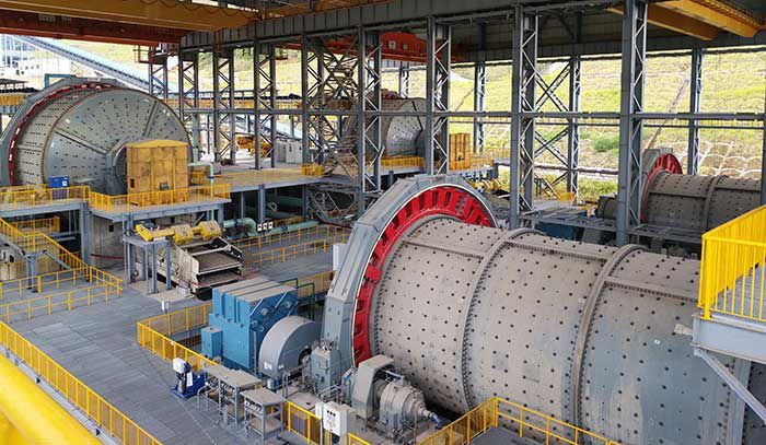
Ball mills are critical equipment in industrial mineral processing, designed to grind raw materials into fine powders for downstream operations. A persistent challenge in ball mill maintenance is the loosening of drum liner nuts due to prolonged exposure to friction, impact, and vibration. Traditional manual tightening methods pose significant safety risks, including mechanical injuries and falls. To address this, I propose a robotic arm system tailored for automated nut tightening on ball mill drums. This study focuses on the kinematic modeling, simulation, and validation of the robotic arm’s motion, leveraging MATLAB Simulink and Simscape Multibody to ensure operational stability and precision.

Mechanical Arm Structure
The robotic arm comprises six primary components (Table 1), designed for flexibility and precision in confined spaces:
| Component | Function | Joint Type |
|---|---|---|
| Base | Supports the arm and enables rotational motion | Revolute |
| Upper Arm | Vertical motion via ball screws | Prismatic |
| Forearm | Horizontal extension/retraction | Prismatic |
| Forearm Deflection Unit | Adjusts orientation to align with nut surfaces | Revolute |
| Forearm Actuator | Extends/retracts the forearm for contact with nuts | Prismatic |
| Tightening Mechanism | Executes nut tightening via rotary sleeves | Revolute |
The arm’s workspace is constrained by the ball mill drum geometry, requiring precise trajectory planning to avoid collisions.
Kinematic Modeling
Forward Kinematics Using D-H Parameters
The Denavit-Hartenberg (D-H) convention was applied to model the robotic arm’s kinematics. The D-H parameters (Table 2) define the spatial relationships between consecutive joints:
| Link ii | θiθi (rad) | didi (m) | ai−1ai−1 (m) | αi−1αi−1 (rad) |
|---|---|---|---|---|
| 1 | θ1θ1 | 0.785 | 0 | 0 |
| 2 | 0 | d2d2 | 0 | 0 |
| 3 | 0 | d3d3 | 0 | −π/2−π/2 |
| 4 | θ4θ4 | 0.176 | 0 | π/2π/2 |
| 5 | 0 | d5d5 | 0 | −π/2−π/2 |
| 6 | θ6θ6 | 0.079 | 0 | 0 |
The transformation matrix between adjacent links is derived as:ii−1T=[cosθi−sinθi0ai−1sinθicosαi−1cosθicosαi−1−sinαi−1−disinαi−1sinθisinαi−1cosθisinαi−1cosαi−1dicosαi−10001]ii−1T=cosθisinθicosαi−1sinθisinαi−10−sinθicosθicosαi−1cosθisinαi−100−sinαi−1cosαi−10ai−1−disinαi−1dicosαi−11
The end-effector pose relative to the base frame is computed by cascading transformations:60T=10T⋅21T⋅32T⋅43T⋅54T⋅65T60T=10T⋅21T⋅32T⋅43T⋅54T⋅65T
Inverse Kinematics
For trajectory planning, inverse kinematics resolves joint variables (θ1,θ4,d2,d3,d5,θ6θ1,θ4,d2,d3,d5,θ6) from the end-effector’s target pose. A geometric approach was adopted to ensure unique solutions. Two cases were analyzed based on proximity to the base:
- Proximal Region (Py≤rPy≤r):
- Forearm retracted (d3<d3,maxd3<d3,max)
- Joint angles:θ1=−θ4=arctanθ1=−θ4=arctand3=Py−d5,min−d6cosθ1d3=cosθ1Py−d5,min−d6
- Distal Region (Py≥rPy≥r):
- Forearm fully extended (d3=d3,maxd3=d3,max)
- Joint angles:θ1=−θ4=−arcsin(Px−d3,max)θ1=−θ4=−arcsin(−d3,maxPx)d5=Py−d3,maxcosθ1−d6d5=Py−d3,maxcosθ1−d6
Vertical displacement d2d2 is resolved as:d2=Pz−d1−d4d2=Pz−d1−d4
MATLAB Simulation and Validation
Simscape Multibody Model
The robotic arm was modeled in Simscape Multibody (Figure 1), incorporating:
- Trajectory Planning: Polynomial trajectories ensured smooth motion between 14 nuts on a 3600×21003600×2100 mm ball mill drum.
- PID Control: Tuned for minimal overshoot and steady-state error.
- Kinematic Constraints: Joint limits enforced to prevent mechanical interference.
Simulation Results
Key performance metrics are summarized below:
| Metric | Joint 2 (Prismatic) | Joint 3 (Prismatic) | Joint 5 (Prismatic) |
|---|---|---|---|
| Max Displacement (m) | 1.05 | 2.298 | 2.474 |
| Max Velocity (m/s) | 0.32 | 0.45 | 0.38 |
| Max Acceleration (m/s²) | 0.18 | 0.25 | 0.21 |
The joint trajectories (Figure 2) exhibit parabolic velocity profiles and sinusoidal acceleration curves, confirming smooth motion with zero initial/final velocities. The end-effector path (Figure 3) demonstrates collision-free navigation across the ball mill drum surface.
Conclusion
This study establishes a robust kinematic framework for a ball mill drum nut tightening robotic arm. The D-H model and geometric inverse kinematics enable precise trajectory tracking, validated through MATLAB simulations. Future work will integrate dynamics and advanced control algorithms to enhance performance under variable loads. This research underscores the potential of automation in improving safety and efficiency in ball mill maintenance.
