
In this article, I explore the innovative lost foam casting process, focusing on its application in producing gray iron castings using slag iron. Lost foam casting, also known as evaporative pattern casting, is a near-net-shape manufacturing technique that has gained significant attention due to its environmental benefits and efficiency. My research delves into the process characteristics, historical development, and simulation techniques, with a particular emphasis on a novel method for utilizing slag iron in gray iron production. Through this study, I aim to demonstrate how lost foam casting can be optimized to reduce costs, improve product quality, and support sustainable manufacturing practices.
Lost foam casting involves creating a foam pattern that replicates the final part, coating it with a refractory material, and embedding it in unbonded sand within a flask. Under vacuum conditions, molten metal is poured, causing the foam to vaporize and be replaced by the metal. This process eliminates the need for cores and complex mold assemblies, simplifying production. The key advantages of lost foam casting include reduced machining allowances, high dimensional accuracy, and the ability to produce complex geometries. However, challenges such as shrinkage defects, slag inclusion, and foam degradation effects must be addressed through careful process design and simulation.
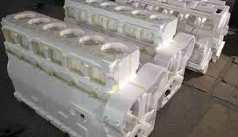
The lost foam casting process begins with pattern-making using expandable polystyrene (EPS), copolymer (STMMA), or polymethyl methacrylate (EPMMA) beads. These materials are selected based on the alloy being cast; for instance, EPS is suitable for aluminum and gray iron, while STMMA and EPMMA are preferred for steel and ductile iron due to their higher decomposition temperatures. The foam pattern is assembled into a cluster, coated with a permeable refractory coating, and dried. After placement in a flask, dry sand is added and vibrated to achieve compaction. During pouring, the vacuum assists in stabilizing the mold and removing decomposition gases. The entire process can be summarized by the following steps: pattern creation, coating application, sand filling, and vacuum-assisted pouring.
To understand the fluid flow and heat transfer in lost foam casting, numerical models are essential. The governing equations for mass, momentum, and energy conservation are applied. The continuity equation for incompressible flow is given by:
$$\frac{\partial u}{\partial x} + \frac{\partial v}{\partial y} + \frac{\partial w}{\partial z} = 0$$
where \( u \), \( v \), and \( w \) are velocity components in the x, y, and z directions, respectively. The momentum equations, derived from the Navier-Stokes equations, account for viscous effects and body forces:
$$\rho \left( \frac{\partial u}{\partial t} + u \frac{\partial u}{\partial x} + v \frac{\partial u}{\partial y} + w \frac{\partial u}{\partial z} \right) = -\frac{\partial P}{\partial x} + \mu \nabla^2 u + F_x$$
$$\rho \left( \frac{\partial v}{\partial t} + u \frac{\partial v}{\partial x} + v \frac{\partial v}{\partial y} + w \frac{\partial v}{\partial z} \right) = -\frac{\partial P}{\partial y} + \mu \nabla^2 v + F_y$$
$$\rho \left( \frac{\partial w}{\partial t} + u \frac{\partial w}{\partial x} + v \frac{\partial w}{\partial y} + w \frac{\partial w}{\partial z} \right) = -\frac{\partial P}{\partial z} + \mu \nabla^2 w + F_z$$
Here, \( \rho \) is density, \( P \) is pressure, \( \mu \) is dynamic viscosity, and \( F_x, F_y, F_z \) are body forces. The energy equation incorporates conduction and latent heat release during solidification:
$$\rho C_p \frac{\partial T}{\partial t} = \lambda \left( \frac{\partial^2 T}{\partial x^2} + \frac{\partial^2 T}{\partial y^2} + \frac{\partial^2 T}{\partial z^2} \right) + \rho L \frac{\partial f_s}{\partial t}$$
where \( C_p \) is specific heat, \( \lambda \) is thermal conductivity, \( T \) is temperature, \( L \) is latent heat, and \( f_s \) is solid fraction. These equations are solved using finite element methods in software like ProCAST to simulate filling and solidification, predicting defects such as shrinkage porosity.
In my investigation of lost foam casting for gray iron, I developed a method to use slag iron—a by-product from steelmaking—as a raw material. Slag iron particles are obtained by crushing and magnetically separating blast furnace slag, typically costing 30-50% less than standard gray iron charges. However, direct melting of slag iron often leads to agglomeration and incomplete dissolution. To overcome this, I introduced a process where standard gray iron is melted first, followed by the addition of slag iron particles. After full melting, elements are adjusted, and purifying/ modifying agents are added to achieve the desired composition. This approach reduces production costs by 1000-1500 CNY per ton and shortens melting time by 10-15 minutes per heat.
The table below compares the chemical composition and microstructure of standard gray iron (HT150) with that produced using slag iron via lost foam casting:
| Element | Standard HT150 | Slag Iron HT150 |
|---|---|---|
| C | 3.0-3.4% | 3.0-3.4% |
| Si | 1.8-2.1% | 1.8-2.1% |
| Mn | 0.5-0.8% | 0.5-0.8% |
| P | <0.2% | <0.2% |
| S | ≤0.12% | ≤0.12% |
| Graphite | Flake, 7-11% | Flake, 7-11% |
| Matrix | Pearlite + Ferrite | Pearlite + Ferrite |
Metallographic analysis confirmed that the microstructure of slag iron-based HT150 is identical to standard material, consisting of pearlite, ferrite, and flake graphite. Mechanical testing revealed a tensile strength of 115 MPa and a bending strength of 325 MPa, meeting the requirements for HT150 gray iron as per GB/T 9439-1988. These results validate the feasibility of using slag iron in lost foam casting without compromising quality.
For the production of a HT150 chassis component via lost foam casting, I evaluated different gating systems: bottom gating, top gating, and a stepped gating approach. Using ProCAST software, I simulated the filling and solidification processes. The filling time for bottom gating was 56.14 seconds, with a slow-fast-slow trend due to foam decomposition and gas pressure effects. Top gating reduced the filling time to 52.14 seconds but introduced slag inclusion risks. The stepped gating system, combining elements of both, achieved a filling time of 41.13 seconds and minimized defects. The solidification simulation used the equivalent specific heat method to handle latent heat:
$$C_e = C_p – L \frac{\partial f_s}{\partial T}$$
where \( C_e \) is the equivalent specific heat. The results showed that stepped gating provided better feeding and reduced shrinkage porosity in thick sections.
The following table summarizes the simulation results for the different gating systems in lost foam casting of the HT150 chassis:
| Gating System | Filling Time (s) | Shrinkage Defects | Slag Inclusion |
|---|---|---|---|
| Bottom Gating | 56.14 | Significant | Low |
| Top Gating | 52.14 | Moderate | High |
| Stepped Gating | 41.13 | Minimal | Low |
Experimental trials confirmed the simulation outcomes, with stepped gating producing sound castings free of major defects. The use of slag iron in this optimized lost foam casting process demonstrated a 90% yield and substantial cost savings, highlighting the potential for industrial adoption.
In conclusion, my research underscores the effectiveness of lost foam casting for gray iron production, particularly when integrated with slag iron utilization and numerical simulation. The stepped gating system proved superior in minimizing defects and enhancing efficiency. Future work should focus on extending this method to more complex geometries and other alloys, as well as refining material properties for simulation accuracy. Lost foam casting, with its environmental and economic benefits, represents a promising direction for advanced manufacturing, and I believe continued innovation in this field will drive further improvements in casting technology.