
Grooved mechanical couplings have displaced flanges and welded joints across much of the liquid and gas pipeline sector. A coupling consists of three elements: an elastomeric sealing ring, a cast clamp shell that compresses the ring into the pipe groove, and locking screws that close the shell. The assembly is fast to install, tolerates less skilled labour, reduces construction cost and, in confined or hazardous environments such as mine piping, avoids hot work entirely. Those advantages depend on the shell being sound: the casting carries the hoop load generated by the internal pressure, and the internal groove must seat against the gasket without interference.
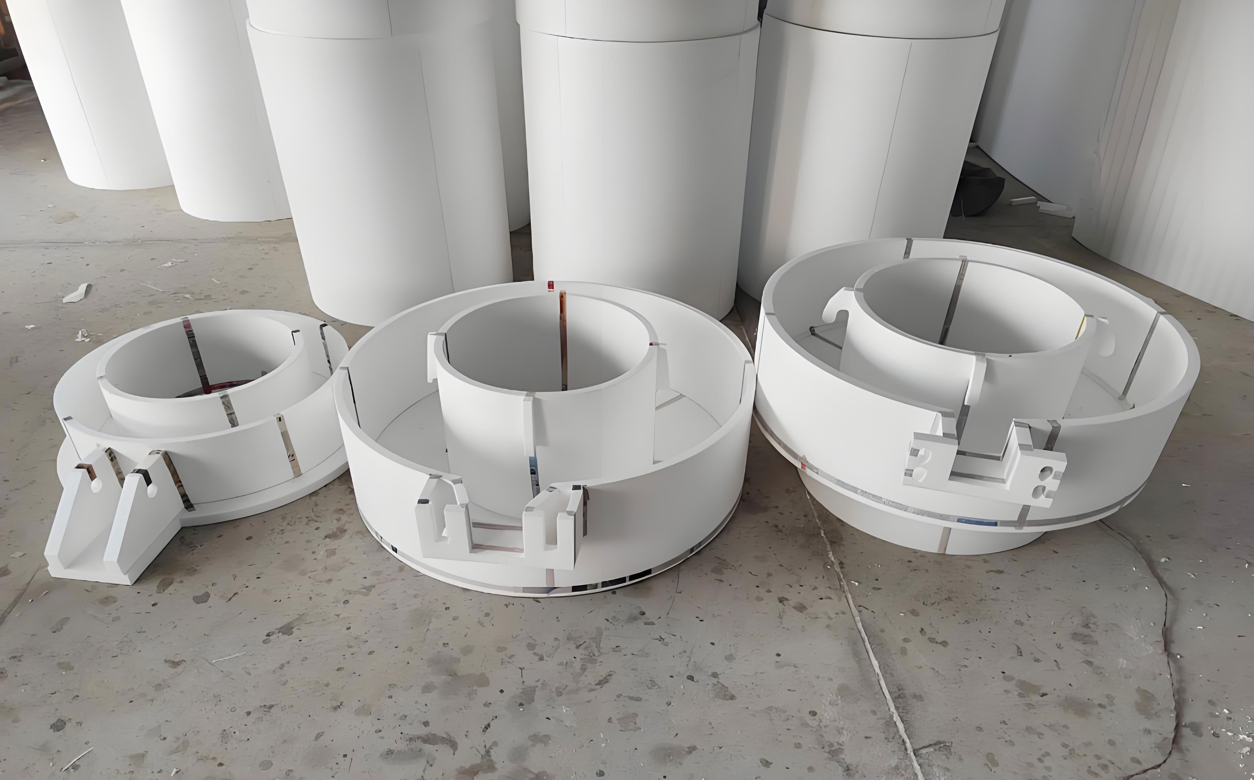
Quality requirements for the cast shell
The DN108 shell is produced in general engineering cast steel, typically ZG27SiMn, ZG270-500 or ZG310-570. Acceptance is governed by both integrity and geometry. Slag inclusions, cold shuts, gas porosity and shrinkage cavities that would degrade mechanical properties are prohibited. Inner and outer surfaces must be smooth, and the internal groove must contact the sealing ring uniformly, free of excess metal, fins and burrs that would prevent the gasket from seating. Markings identifying manufacturer, size and pressure rating must remain legible, and the anti-corrosion coating must be continuous and well bonded, without blistering or local build-up.
Performance is verified by a hydrostatic test: the assembled joint must withstand 0.15 MPa for 10 min without leakage. Where higher service pressures are required, the wall thickness around the bolt holes is increased, since this region is the mechanically weakest section of the shell.
Process route and parameter window
The shell is produced by lost foam casting from expanded polystyrene (EPS), with an unboned refractory coating, in unbonded ceramic sand under vacuum. Because pattern decomposition, coating permeability, sand compaction and vacuum level interact, the process window has to be fixed jointly rather than optimised one variable at a time. The parameters below were established by production trials and defect analysis on the DN108 part.
| Stage | Parameter | Value |
|---|---|---|
| EPS pattern | Bead diameter | 1.5–2.0 mm |
| Pre-expansion | 5 min at 40 °C | |
| Moulding | 80 °C, 20 s | |
| Blowing agent content; dried pattern mass | 5.5%; 0.018–0.020 kg | |
| Water-based slurry | Refractory filler | 40% zircon flour + 40% quartz flour |
| Additions (mass fraction) | 2% lithium bentonite, 1.5% sodium carboxymethyl cellulose, 3% water-soluble phenolic resin, 0.02% OP-10 wetting agent, 0.02% n-butanol defoamer, 0.02% sodium benzoate preservative, balance water | |
| Coating | Coats; thickness; drying | 2 coats; 1.0–1.2 mm total; 8 h per coat at 50–55 °C, relative humidity below 30% |
| Gating system | Sprue; runners; ingates | 1 × 75 × 60 mm; 3 × 60 × 40 mm; 60 × 10 × 10 mm (60 castings per flask) |
| Moulding | Bottom sand layer; vibration; ceramic sand | 100 mm; 40 s, 3 cycles, 10 m/s² at 30 Hz; angular coefficient below 1.1 |
| Pouring | Vacuum; tapping and pouring temperature | 0.05 MPa; 1690–1700 °C tapped, 1660–1670 °C poured |
Defect mechanisms and countermeasures
Four defect types dominate production of this component: misruns, excess metal at holes and corners, distortion along the 108 mm diameter, and scattered gas porosity. Each maps onto a distinct set of process variables.
| Defect | Typical location | Dominant mechanism | Corrective action |
|---|---|---|---|
| Misrun | Middle of the runner | Excessively fine EPS beads raise pattern density and therefore the volume of decomposition gas per unit of metal front; back pressure arrests filling | Hold bead size at 1.5–2.0 mm, control investment filling so compaction is moderate, check dried pattern mass |
| Misrun | Runner end | Heat consumed by pattern vaporisation (roughly 50 °C loss) combined with low pouring temperature or slow pouring rate | Tap at 1690–1700 °C, pour at 1660–1670 °C, keep the pouring cup full throughout |
| Excess metal (fin) | Bolt holes | Patterns invested vertically leave the hole axis horizontal; sand cannot compact inside the hole, the vacuum draws metal through a ruptured coating | Invest horizontally so the hole axis faces the sand-filling direction |
| Excess metal (fin) | Corners and ribs | Prolonged vibration abrades the coating where it is thinnest; immersion coating traps bubbles at sharp edges | Limit vibration to 40 s, use ceramic sand with angular coefficient below 1.1, lower the pattern slowly along the semicircular direction |
| Distortion | Across the 108 mm diameter | Wet coating softens the pattern and drying position fixes the distortion; early shakeout causes contraction | Dedicated drying racks supporting the pattern laterally; shakeout no earlier than 4 h after pouring |
| Gas porosity | Random | Thick or viscous coating restricts permeability; gating fills too fast for the venting time; pouring rate mismatched to vacuum level; incomplete drying | Coating 1.0–1.2 mm, verified gating without choking, pouring time no longer than the time needed to vaporise and evacuate the pattern |
Interpreting the misrun data
The two misrun modes require different corrections even though the visible result is the same. At the middle of the runner, the cause lies upstream in pattern production: finer beads give a denser foam, more polystyrene per unit volume, and therefore a larger gas load precisely where the metal front is still accelerating. The remedy is a bounded bead size combined with controlled filling of the moulding machine, verified indirectly through the mass of the dried pattern, which should fall between 0.018 kg and 0.020 kg for this component.
At the runner end, the limiting factor is thermal. Vaporisation of the foam removes heat from the advancing metal, and the loss is on the order of 50 °C. A melt tapped at 1690–1700 °C and poured at 1660–1670 °C retains enough superheat to reach the last ingate; a lower tapping temperature or a slow pour does not, and the front solidifies before filling is complete. Maintaining a full pouring cup is part of the same control, since it keeps the ferrostatic head, and hence the fill rate, constant.
Coating and compaction as coupled variables
Several defects trace back to the same coating layer. Excess metal at corners arises when vibration thins the coating by abrasion, and bubbles entrained during immersion coating create local weak spots that the metal penetrates. Both are avoided by a slower immersion path that lets slurry flow along the raised groove, and by capping the vibration cycle at 40 s with a well-graded ceramic sand. A viscous slurry containing entrained bubbles produces the same finning elsewhere on the casting; reducing the inorganic binder content improves permeability and suppresses foam formation, and a defoamer provides additional control.
Porosity, by contrast, is a venting problem. A coating thicker than about 1.2 mm, or one applied with excessive viscosity, slows gas escape; a gating system that fills the cavity faster than gas can be removed through the coating and the vacuum system produces the same effect. The practical criterion is that total pouring time must not exceed the time required to vaporise the pattern and evacuate the products through the coating. This couples the gating layout — one sprue of 75 × 60 mm, three runners of 60 × 40 mm and sixty ingates of 10 × 10 mm per flask — to the vacuum level of 0.05 MPa and to the drying schedule of 8 h per coat at 50–55 °C.
Production implications
Distortion control is largely a handling discipline rather than a metallurgical one. Coated EPS patterns lose stiffness, so the geometry of the drying rack determines the as-dried shape; side support prevents load being carried across the 108 mm diameter, and a minimum 4 h interval before shakeout avoids contraction distortion during rapid cooling. Once bead size, slurry formulation, coating thickness, vibration parameters, vacuum and pouring temperature are fixed within the windows above, the defect population on the DN108 shell becomes stable, which is the precondition for extending the same parameter set to other sizes in the coupling range.