
In my experience with foundry processes, the adoption of lost foam casting for producing thick-section ductile iron components like vacuum pump housings has proven highly effective. This method addresses common issues such as leakage and wear in welded steel versions, which fail under prolonged exposure to water and abrasive particles. By leveraging lost foam casting, I have achieved precise dimensional control and superior material properties in complex geometries. The vacuum pump housing discussed here has a maximum outer dimension of approximately 864 mm in diameter and 637 mm in height, with a wall thickness of 35 mm and a weight of 425 kg. The material specification requires QT600-3 grade ductile iron, emphasizing leak-proof integrity. This article delves into the comprehensive lost foam casting process, from design and simulation to production and validation, highlighting how this technique ensures high-quality outcomes.
The lost foam casting process begins with a detailed design phase. I focused on creating a robust gating system to facilitate smooth filling and effective feeding. Using a top-gating approach with a semi-open system, the gating ratio was set as follows: the total cross-sectional area of the sprue (ΣF_sprue) to the runner (ΣF_runner) to the ingates (ΣF_ingate) is 1:1.4:1.2. Specifically, the sprue diameter is 50 mm, the runner cross-section is 75 mm × 75 mm, and each ingate measures 40 mm × 140 mm. Six risers, each 120 mm × 120 mm × 140 mm, are positioned uniformly on the top surface to promote directional solidification and mitigate shrinkage defects. In lost foam casting, the use of external chills is impractical due to mold constraints, and internal chills risk poor fusion; thus, risers are essential for compensation. Two of these risers serve as hot risers, where molten metal enters the cavity, while the others fill as the metal level rises, collectively ensuring adequate feeding during solidification.
To validate this design, I employed MAGMA software for numerical simulation of the filling and solidification stages. The results confirmed that the top-gating system allows metal to enter the cavity smoothly, descending to the bottom before rising progressively. This minimizes turbulence and supports sequential solidification, with the risers remaining liquid longest to compensate for volumetric shrinkage. The simulation equations governing fluid flow and heat transfer in lost foam casting can be summarized as follows: the continuity equation $$ \frac{\partial \rho}{\partial t} + \nabla \cdot (\rho \mathbf{v}) = 0 $$ and the Navier-Stokes equation $$ \rho \left( \frac{\partial \mathbf{v}}{\partial t} + \mathbf{v} \cdot \nabla \mathbf{v} \right) = -\nabla p + \mu \nabla^2 \mathbf{v} + \mathbf{f} $$, where \( \rho \) is density, \( \mathbf{v} \) is velocity, \( p \) is pressure, \( \mu \) is viscosity, and \( \mathbf{f} \) represents body forces. For solidification, the energy equation $$ \frac{\partial (\rho h)}{\partial t} + \nabla \cdot (\rho h \mathbf{v}) = \nabla \cdot (k \nabla T) + S $$ is applied, with \( h \) as enthalpy, \( k \) as thermal conductivity, \( T \) as temperature, and \( S \) as a source term accounting for latent heat. The simulation outputs showed no significant isolated liquid zones, indicating that graphite expansion could counter minor micro-shrinkage, thus affirming the reliability of the lost foam casting process for this application.
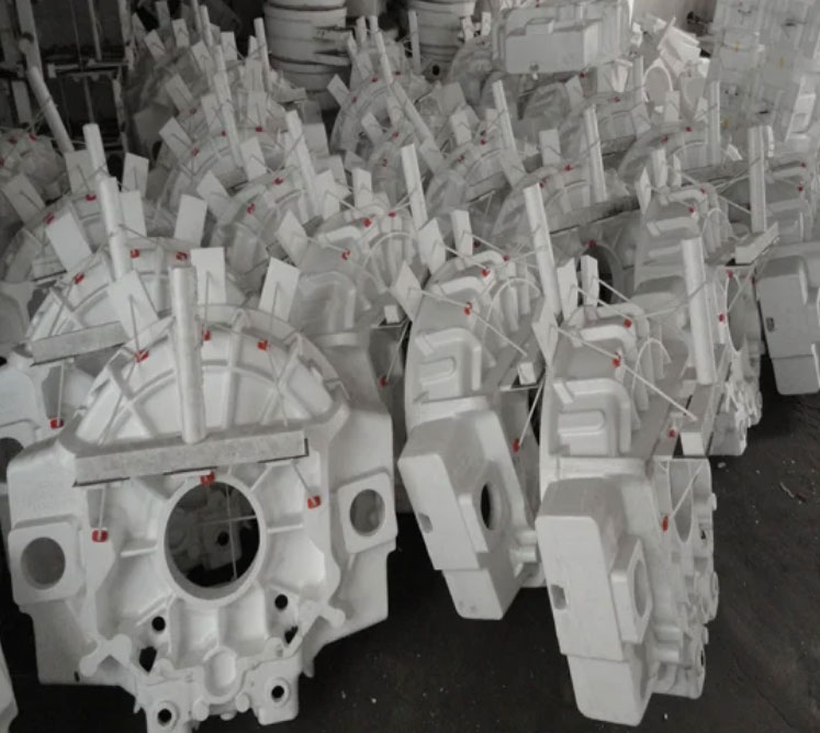
Moving to pattern fabrication, the large size of the vacuum pump housing necessitated segmenting the foam pattern into multiple pieces for manageable production. I used CAD software to decompose the geometry into 20 segments: 12 for the cylindrical body and 8 for the end flanges, with fillet radii of 10 mm. Automated CNC cutting ensured precision, and the parts were manually assembled on a glass plate aligned to a central reference. Adhesive and paper tape sealed the joints to prevent coating infiltration during subsequent steps. Reinforcement with 15 mm × 15 mm wooden strips at both ends prevented distortion, and fiber rods secured the riser attachments. This meticulous approach in lost foam casting guarantees dimensional accuracy and pattern integrity, crucial for avoiding defects in the final casting.
Coating application is a critical step in lost foam casting to maintain mold stability during pouring. I immersed the assembled pattern in a ceramic coating slurry, rotating it slowly to cover all surfaces evenly. Additional hand-pouring ensured hard-to-reach areas were coated. The coating was applied in four layers, with a Baume density controlled between 69 and 71 °Bé to achieve sufficient thickness and strength. After coating, the pattern was dried in a dedicated oven to remove moisture. This process creates a permeable barrier that withstands the thermal shock of molten iron while allowing gases to escape, a key advantage of lost foam casting.
For molding, I placed the coated pattern in a 1200 mm × 1000 mm × 1300 mm flask and used vibration-assisted sand filling to compact the dry silica sand around it. The vibration time was set to 90 seconds to achieve optimal density without pattern damage. In lost foam casting, the sand mold requires no binders, reducing environmental impact and simplifying shakeout. The flask was then subjected to a vacuum of -0.05 to -0.06 MPa during pouring to extract decomposition gases and prevent defects, with pressure maintained for one hour post-pouring to ensure solidification integrity.
The melting and treatment phase involved precise control over composition and nodularization. The target chemical composition for the ductile iron is outlined in the table below:
| Element | Content (wt%) |
|---|---|
| C | 3.7 |
| Si (post-nodularization) | 2.4 |
| Mn | 0.5 |
| S | 0.015 |
| P | 0.05 |
| Mg (residual) | 0.05 |
| Sn | 0.06 |
I utilized a cored wire injection method for nodularization, which is highly efficient in lost foam casting due to minimal oxidation and high alloy recovery. The FeSiMg25Re3 nodularizer was added at 0.7% via double-wire injection into a 700 kg ladle, with inoculation using 0.3% preconditioner and 0.2% 75FeSi composite. The reaction can be modeled using the equation $$ \text{Mg recovery} = \frac{\text{Mg absorbed}}{\text{Mg added}} \times 100\% $$, which typically exceeds 90% in this setup. Pouring temperature was maintained between 1430°C and 1450°C; if exceeded, cold iron additions were used to cool the metal. After treatment, slag was removed promptly, and the metal was transported for pouring.
Post-casting evaluation involved mechanical and metallurgical testing of attached specimens. The results are summarized in the following table:
| Property | Value |
|---|---|
| Nodularity Grade | 2 |
| Graphite Size Grade | 7 |
| Pearlite Volume Fraction (%) | 65 |
| Cementite Volume Fraction (%) | ≤1.0 |
| Phosphide Eutectic Volume Fraction (%) | ≤0.5 |
| Tensile Strength (MPa) | 641 |
| Elongation (%) | 3.5 |
These results confirm that the lost foam casting process achieved the required QT600-3 specifications, with a dense microstructure free from shrinkage or leakage. The riser necks showed no defects, and machining revealed sound surfaces, validating the process design. The success of this lost foam casting application underscores its suitability for thick-section ductile iron components, offering advantages in precision and quality.
In conclusion, the lost foam casting method has demonstrated exceptional capability in producing high-integrity vacuum pump housings. The segmented foam pattern approach, combined with advanced gating and riser design, ensures dimensional accuracy and structural soundness. The cored wire nodularization technique enhances treatment efficiency, meeting material demands effectively. Through simulation and practical execution, the lost foam casting process facilitates controlled filling and solidification, resulting in leak-proof castings. This experience reinforces lost foam casting as a viable solution for complex, heavy-section iron castings in industrial applications.
Further optimization in lost foam casting could involve adjusting coating properties or refining pattern segmentation for even larger components. The integration of real-time monitoring during pouring might enhance process control. Overall, the lost foam casting technique continues to evolve, offering sustainable and efficient manufacturing pathways for demanding castings.