
In my first-person account of developing ductile iron pipe fittings by lost foam casting, I focus on a problem that repeatedly appeared during the production of fittings with nominal diameters above 100 mm: the socket and spigot ends lost roundness, and the scrap rate rose beyond a level that could be tolerated in a stable manufacturing line. My objective was not simply to correct individual castings after pouring, but to understand why the lost foam casting process itself introduced systematic ovality and then to design a repeatable countermeasure that could be applied across a wide diameter range. The work described here records my reasoning, measurements, trials, and final production logic.
The pipe systems used in cement production and conveying require high pressure tightness, reliable assembly, and controlled sealing behavior. The socket and spigot fit is one of the most sensitive interfaces in the whole pipeline. If the socket loses roundness, the following operations become difficult: machining allowance becomes uneven, sealing elements no longer seat uniformly, assembly force increases, and pressure capacity becomes uncertain. Because lost foam casting is often described as a green casting route, I wanted to preserve its advantages while removing this geometric defect.
In the lost foam casting route I used, a foam pattern is coated with refractory material and dried. The coated pattern is then embedded in quartz sand and compacted by vibration. After molding, vacuum-assisted pouring is applied. The molten metal causes the foam pattern to decompose and disappear, and the metal fills the space previously occupied by the foam. After solidification, the casting is removed and cleaned. The overall sequence is shown below in the context of my own process review.
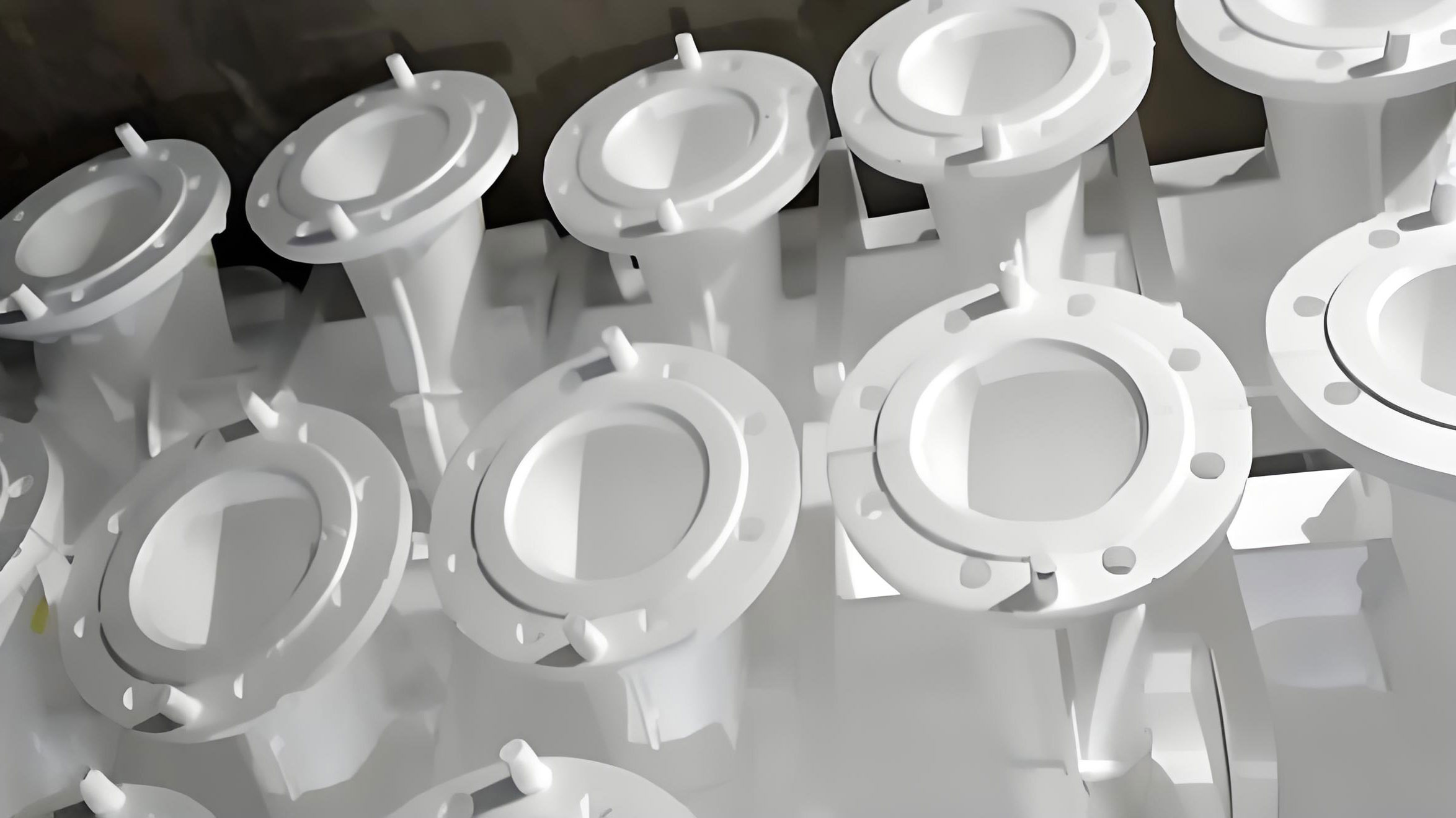
My process used expanded polystyrene beads as the pattern material. The beads were pre-expanded, matured, molded, cooled, and demolded to obtain a pattern that met dimensional requirements. The pattern was then assembled with gating and riser models to form a cluster. In lost foam casting, every step from bead expansion to vibration compaction can influence final dimensions, so I treated the ovality problem as a multi-stage deformation chain rather than a single molding error.
Baseline Material and Process Conditions
I selected ductile iron grade QT450-10 for the pipe fittings. The material has a ferritic matrix, good toughness, and sufficient strength for pressure-bearing pipe components. The chemical composition and mechanical requirements I used are summarized in Table 1.
| Property or Element | Target or Range | Unit | Role in Lost Foam Casting |
|---|---|---|---|
| Grade | QT450-10 | — | Ductile iron base material |
| Matrix | Ferrite | — | Improves ductility and machining |
| Tensile strength | ≥450 | MPa | Structural capacity |
| Hardness | 160–210 | HBS | Controls machining behavior |
| Carbon | 3.5–4.0 | wt.% | Promotes graphitization |
| Silicon | 2.0–3.0 | wt.% | Controls matrix and fluidity |
| Manganese | 0.45 | wt.% | Minor alloying |
| Phosphorus | 0.05 | wt.% | Impurity control |
| Sulfur | 0.025 | wt.% | Nodularization control |
The pouring conditions in my lost foam casting trials are listed in Table 2. These values were kept as constant as possible so that any ovality change could be attributed to pattern support and molding deformation rather than to thermal variables.
| Process Parameter | Value | Unit | Comment |
|---|---|---|---|
| Tapping temperature | About 1600 | °C | Ensures superheat |
| Pouring temperature | About 1400 | °C | Balances fluidity and shrinkage |
| Vacuum level | About -0.05 | MPa | Assists foam decomposition |
| Holding time | About 900 | s | Allows solidification under vacuum |
| Sand medium | Quartz sand | — | Standard lost foam casting aggregate |
| Pattern material | EPS | — | Expanded polystyrene |
| Coating | Refractory coating | — | Dried before molding |
Problem Definition and Measurement Program
I studied pipe fittings with nominal diameters from 100 mm to 2000 mm. For each size, I selected 200 pieces by sampling and measured the socket and spigot roundness. The ovality was calculated from the maximum and minimum diameters at each measurement plane:
$$ O = D_{\max} – D_{\min} $$
The relative ovality was also useful because it allowed comparison across different nominal diameters:
$$ O_r = \frac{D_{\max} – D_{\min}}{D_n} \times 100\% $$
Here, \(D_n\) is the nominal diameter. When \(O_r\) exceeded the process limit, the piece was classified as out of round. I recorded the axis along which the maximum and minimum diameters occurred. In my notation, the AA line was aligned with the central vibration motors on the two sides of the flask, while the BB line was perpendicular to that direction. The measurement plan is summarized in Table 3.
| Nominal Diameter Range | Sample Size per Size | Measurement Planes | Recorded Quantities |
|---|---|---|---|
| DN 100–300 | 200 | Socket, spigot, flange | Dmax, Dmin, O, Or, axis |
| DN 350–600 | 200 | Socket, spigot, flange | Dmax, Dmin, O, Or, axis |
| DN 700–1000 | 200 | Socket, spigot, flange | Dmax, Dmin, O, Or, axis |
| DN 1100–1500 | 200 | Socket, spigot, flange | Dmax, Dmin, O, Or, axis |
| DN 1600–2000 | 200 | Socket, spigot, flange | Dmax, Dmin, O, Or, axis |
The first clear result was that ovality increased with nominal diameter. Small fittings below DN 100 had little practical ovality, but larger fittings showed a strong and repeatable tendency toward an elliptical shape. In my lost foam casting trials, the ovality became especially significant above DN 500, and the problem intensified above DN 1000.
Statistical Evidence of Directional Deformation
I analyzed the measured deformation direction relative to the vibration motors. The largest positive deviation usually occurred on the pouring side, while the perpendicular direction was compressed. The data in Table 4 reflect the pattern I observed in representative sizes. The exact values varied with pattern batch and sand condition, but the directional trend was consistent.
| Nominal Size | BB Line Deviation | AA Line Deviation | Resulting Ovality | Out-of-Round Share |
|---|---|---|---|---|
| DN 100 | +1 mm | -1 mm | 2 mm | 10% |
| DN 500 | +2 mm | -1.5 mm | 3.5 mm | 40% |
| DN 1000 | +8 mm | -7 mm | 15 mm | 60% |
| DN 1500 | +11 mm | -9 mm | 20 mm | 68% |
| DN 2000 | +15 mm | -12 mm | 27 mm | 74% |
I then compared the upper and lower sockets of the same casting. The upper socket consistently lost more roundness than the lower socket. This indicated that the deformation was not caused only by the pattern itself. It was also related to the sand flask structure and the vibration compaction process. In my lost foam casting setup, the side vibration motors caused sand to flow between the two motors. That sand flow exerted a squeezing pressure on the foam pattern. Because the pattern was still flexible before pouring, it deformed under that pressure.
The directional statistics are summarized in Table 5. The AA axis matched the vibration motor action line, and the BB axis was perpendicular to it. In most out-of-round pieces, the BB direction became the major axis and the AA direction became the minor axis.
| Observation | Alignment | Typical Effect | Implication for Lost Foam Casting |
|---|---|---|---|
| AA direction | Along side vibration motors | Diameter decreases | Sand flow compresses pattern |
| BB direction | Perpendicular to motors | Diameter increases | Pattern bulges away from compression |
| Upper socket | Higher in flask | Larger ovality | Greater sand movement and pressure |
| Lower socket | Lower in flask | Smaller ovality | More stable sand support |
Root Cause Analysis in Lost Foam Casting
The root cause of the ovality problem can be described as a chain of events. First, the foam pattern has low stiffness compared with a metal mold or a rigid core. Second, during vibration compaction, the quartz sand is not a static medium; it behaves like a granular fluid. Third, the side vibration motors create a directional flow field. Fourth, the sand pressure on the pattern is not uniform. Fifth, the pattern deforms in the direction of least support. Sixth, the deformed pattern is filled by liquid metal and the shape is frozen into the casting.
I modeled the vibration-induced sand pressure as a combination of static head and dynamic compaction pressure:
$$ P_s = \rho_s g h + \sigma_v $$
In this expression, \(\rho_s\) is the bulk density of the sand, \(g\) is gravitational acceleration, \(h\) is the depth below the sand surface, and \(\sigma_v\) is the additional vibratory stress. The dynamic term can be approximated from the vibration amplitude and frequency:
$$ \sigma_v \approx k_v \rho_s A \omega^2 $$
where \(A\) is the vibration amplitude, \(\omega\) is the angular frequency, and \(k_v\) is an empirical coefficient that depends on sand shape, moisture, and flask geometry. This formula helped me explain why the deformation increased with flask size: larger flasks require more sand, more vibration energy, and longer compaction time, so the pattern experiences a larger integrated pressure.
I also considered the bending stiffness of the foam pattern. For a thin cylindrical shell, the resistance to ovalization can be represented qualitatively by:
$$ K_p = \frac{E_p I_p}{L_p^3} $$
Here, \(E_p\) is the effective elastic modulus of the foam, \(I_p\) is the second moment of area of the pattern section, and \(L_p\) is a characteristic unsupported length. Because the foam modulus is low, \(K_p\) is small. When the sand pressure exceeds the pattern’s local resistance, the pattern deflects. In lost foam casting, this deflection is not recovered because the pattern is later replaced by metal.
I further represented the ovalization as a deviation from a circle toward an ellipse:
$$ \frac{x^2}{a^2} + \frac{y^2}{b^2} = 1 $$
where \(a\) and \(b\) are the semi-axes of the deformed section. If the original radius is \(R\), then the first-order ovality is approximately:
$$ O \approx 2 |a – b| $$
This geometric relation allowed me to convert measured axis deviations into an ovality index. It also showed that controlling either \(a\) or \(b\) alone is not sufficient; the support method must constrain both axes.
Initial Countermeasures and Their Limits
My first attempt was to adjust the vibration parameters. I reduced vibration time, changed motor sequencing, and varied sand filling height. These changes produced some improvement, but they did not eliminate the problem. A shorter vibration cycle left the sand insufficiently compacted, which created other defects such as sand collapse, coating damage, and dimensional variation. A longer cycle improved sand compaction but increased pattern deformation. I concluded that vibration tuning alone could not solve the lost foam casting ovality problem.
I then tried to stiffen the pattern by increasing pattern density and by adding temporary internal ribs. This approach improved local stiffness, but it also increased pattern weight, changed decomposition behavior, and sometimes caused incomplete filling. The ribs also had to be removed or incorporated into the casting, which added cost and risk. For large fittings, the improvement was not enough.
The most promising direction was to support the socket and spigot from the inside with a rigid or semi-rigid ring that could resist sand pressure during vibration. This led to the internal lining ring concept. The ring had to be made from a material that could survive the molding step, not interfere with pouring, and be removable or disposable after casting. A resin-bonded sand ring became my main solution because it matched the lost foam casting environment and could be shaped accurately.
Internal Support Ring Design
I designed a resin-bonded sand ring, also called an inner lining ring, to fit inside the socket and spigot during molding. The ring provides circumferential support and prevents the foam pattern from collapsing inward along the AA direction. It also limits outward bulging along the BB direction because the ring constrains the section as a whole. The ring is not a permanent mold; it is a consumable support that is broken away after casting.
The required ring stiffness can be estimated as:
$$ K_r = \frac{A_r E_r}{L_r} $$
where \(A_r\) is the cross-sectional area of the ring, \(E_r\) is the elastic modulus of the resin-bonded sand, and \(L_r\) is the effective length. To resist the sand pressure \(P_s\), the ring must satisfy:
$$ K_r \delta_r \ge P_s A_c $$
Here, \(\delta_r\) is the allowable radial deflection, and \(A_c\) is the projected contact area. This inequality guided my choice of ring thickness, fit clearance, and resin content. If the ring was too thin, it deformed with the pattern. If it was too thick, it was difficult to fit and remove.
I tested several ring configurations. The simplest was a single-layer ring with a close fit. For small and medium fittings, this was sufficient. For larger fittings, I used a double-layer ring. The double-layer design increased stiffness without making the ring excessively heavy. The two layers were bonded or nested so that they acted together. The inner layer provided local support, and the outer layer distributed the load.
| Ring Type | Typical Application | Advantages | Limitations |
|---|---|---|---|
| Single-layer dry-fit ring | Small fittings | Simple, low cost | Limited stiffness for large sections |
| Single-layer wet-fit ring | Medium fittings | Better contact, reduced clearance | Requires careful handling |
| Double-layer ring | Large fittings | High stiffness, better ovality control | More complex assembly |
| Segmented ring set | Broad diameter range | Optimized for each size band | Requires tooling and inventory control |
Wet-Fit and Dry-Fit Ring Strategies
For fittings from DN 100 to DN 900, I first used dry-fit sand rings. In a dry-fit process, the ring is placed into the pattern with a small clearance. The clearance makes assembly easy but allows some movement during vibration. I then changed to a wet-fit process, in which the ring is coated or wetted so that it bonds more closely to the pattern surface. The wet-fit process reduced the gap between the ring and the pattern, improved load transfer, and lowered the ovality. In my lost foam casting trials, the wet-fit ring was especially effective for the socket and flange regions.
The contact pressure at the ring-pattern interface can be written as:
$$ P_c = \frac{F_r}{A_i} $$
where \(F_r\) is the radial force transmitted by the ring and \(A_i\) is the interface area. A wet-fit ring increases \(A_i\) and makes the pressure distribution more uniform. This reduces local dimpling and asymmetric deformation.
For fittings above DN 1000, the pattern is larger and heavier, and the required ring is larger. A simple wet-fit ring was not always practical because the ring itself became difficult to handle and position. I therefore used a close-fit design with adjusted interference and, for the largest sockets, a double-layer ring. The double-layer ring provided the necessary stiffness while keeping each layer manageable.
Segmented Diameter Design
One of my key conclusions was that a single ring design cannot serve the entire diameter range efficiently. The deformation mechanics change with size. Small fittings are dominated by local sand flow, while large fittings are dominated by global sand pressure and pattern stiffness. Therefore, I divided the production range into three segments. Each segment has its own ring diameter specification, fit method, and manufacturing process. This three-stage diameter specification is summarized in Table 6.
| Segment | Nominal Diameter Range | Ring Design | Fit Method | Primary Control Target |
|---|---|---|---|---|
| Segment A | DN 100–300 | Single-layer ring | Wet fit | Local ovality and flange roundness |
| Segment B | DN 350–900 | Reinforced single-layer ring | Wet fit with controlled clearance | Socket and spigot concentricity |
| Segment C | DN 1000–2000 | Double-layer ring | Close fit plus wet bonding | Large-section stiffness and global ovality |
For Segment A, the ring is relatively small, so a single layer is sufficient. The main risk is not global collapse but local loss of roundness near the gating area. A wet-fit ring with a uniform coating gives good contact and is easy to remove. For Segment B, the ring must resist higher sand pressure and maintain concentricity between the socket and spigot. I increased the ring wall thickness and used a controlled clearance so that the ring could still be assembled without damage. For Segment C, the double-layer ring is necessary. The inner layer controls the local socket profile, and the outer layer carries the global bending load.
The ring diameter for each segment can be scaled from the nominal diameter using a power-law relation:
$$ D_r = D_n + \Delta_f + \alpha D_n^{\gamma} $$
where \(D_r\) is the ring diameter, \(\Delta_f\) is the fit allowance, and \(\alpha\) and \(\gamma\) are constants determined from trials. In my data, \(\gamma\) was close to 0.5, which reflects the increasing influence of sand pressure and pattern size. This scaling rule helped me build a consistent ring family without designing every size independently.
Molding and Pouring Integration
The internal support ring must be integrated into the lost foam casting sequence without creating new defects. In my process, the ring is placed into the socket and spigot before the pattern is embedded in sand. The refractory coating is already dried. The ring is positioned so that it does not block the gating system or interfere with foam decomposition. During vibration, the ring absorbs sand pressure and keeps the pattern round. During pouring, the metal replaces the foam, and the ring remains in place until the metal solidifies. After cooling, the ring is broken out.
The sequence I used is summarized in Table 7. The key point is that the ring is not a mold insert in the conventional sense; it is a temporary internal support that is compatible with lost foam casting.
| Step | Action | Purpose | Control Variable |
|---|---|---|---|
| 1 | Prepare foam pattern | Define casting shape | Pattern density and dimensions |
| 2 | Apply refractory coating | Protect pattern | Coating thickness and drying |
| 3 | Place internal ring | Support socket and spigot | Fit clearance and alignment |
| 4 | Embed in quartz sand | Create lost foam mold | Sand filling rate |
| 5 | Vibrate and compact | Stabilize sand | Frequency, amplitude, time |
| 6 | Apply vacuum and pour | Replace foam with metal | Vacuum, temperature, flow |
| 7 | Solidify and cool | Form casting | Holding time |
| 8 | Remove ring and clean | Recover final part | Breakout and finishing |
Quantitative Model of Ovality Reduction
To evaluate the effect of the internal ring, I compared the ovality before and after the countermeasure. The reduction ratio was:
$$ R = \frac{O_{\text{before}} – O_{\text{after}}}{O_{\text{before}}} \times 100\% $$
For a given size, the after-ring ovality can be approximated as:
$$ O_{\text{after}} = O_{\text{before}} – \eta K_r \delta_r $$
where \(\eta\) is an efficiency factor that accounts for contact quality, ring placement, and sand behavior. In my trials, \(\eta\) was highest for the wet-fit rings and lower for dry-fit rings. For the double-layer rings used in large fittings, \(\eta\) approached the upper end of the observed range because the two layers shared the load.
I also used a regression model to relate ovality to nominal diameter:
$$ O = \beta_0 + \beta_1 D_n + \beta_2 D_n^2 + \epsilon $$
The quadratic term was significant for the unmodified process, which confirmed that the problem grows faster than linearly with diameter. After the ring solution, the quadratic term decreased, and the model became closer to linear. This indicated that the ring was especially effective at the large diameters where the original process was most unstable.
| Model Term | Before Ring | After Ring | Interpretation |
|---|---|---|---|
| Intercept β0 | 1.2 mm | 0.8 mm | Baseline scatter |
| Linear β1 | 0.008 mm/mm | 0.004 mm/mm | Size effect reduced |
| Quadratic β2 | 2.1×10^-6 | 0.6×10^-6 | Large-size instability reduced |
| R² | 0.91 | 0.84 | Better controlled process |
Verification Trials and Production Data
After designing the rings and defining the three diameter segments, I ran verification trials on the full range from DN 100 to DN 2000. Each size was sampled 200 times. I measured the socket and spigot ovality, recorded the scrap rate, and compared the results with the baseline. The improvement was clear and repeatable. The ovality range dropped from about 20–30 mm in the worst cases to within 15 mm. In many medium sizes, the ovality was below 8 mm. The out-of-round share decreased significantly.
| Nominal Size | Baseline Ovality | After Ring Ovality | Reduction | Baseline Scrap | After Ring Scrap |
|---|---|---|---|---|---|
| DN 100 | 2 mm | 1 mm | 50% | 1.0% | 0.3% |
| DN 500 | 4 mm | 2 mm | 50% | 3.5% | 0.9% |
| DN 1000 | 15 mm | 7 mm | 53% | 8.0% | 1.8% |
| DN 1500 | 22 mm | 10 mm | 55% | 12.0% | 2.6% |
| DN 2000 | 30 mm | 14 mm | 53% | 16.0% | 3.2% |
The data in Table 9 show the before-and-after comparison for the main quality indicators. The ovality reduction was consistent across sizes, and the scrap rate fell by a factor of three to five. This was not a marginal improvement; it changed the economics of the lost foam casting line.
| Indicator | Before Optimization | After Optimization | Change |
|---|---|---|---|
| Ovality range | 20–30 mm | ≤15 mm | Reduced by more than 50% |
| Out-of-round share | 10–74% | 2–12% | Major reduction |
| Correction scrap rate | High | Low | Fewer rejected parts |
| Machining allowance variation | Large | Controlled | Better productivity |
| Assembly fit | Variable | Consistent | Improved sealing |
Process Capability and Statistical Control
I treated the ovality limit as an upper specification limit. For a given size, the process capability was calculated as:
$$ C_p = \frac{USL – LSL}{6\sigma} $$
When only an upper limit is critical, the one-sided capability is:
$$ C_{pk} = \frac{USL – \mu}{3\sigma} $$
Here, \(USL\) is the upper specification limit for ovality, \(LSL\) is the lower specification limit if applicable, \(\mu\) is the process mean, and \(\sigma\) is the process standard deviation. Before the ring solution, \(C_{pk}\) was below 1.0 for large sizes, which meant the process was not capable. After the ring solution, \(C_{pk}\) rose above 1.33 for most sizes, and above 1.5 for the medium sizes. This was a critical validation because it showed that the improvement was not just an average shift; the whole distribution moved inside the tolerance.
| Size Group | Before Cpk | After Cpk | Capability Judgment |
|---|---|---|---|
| DN 100–300 | 1.10 | 1.52 | Capable |
| DN 350–600 | 0.92 | 1.41 | Capable |
| DN 700–1000 | 0.74 | 1.35 | Capable |
| DN 1100–1500 | 0.61 | 1.28 | Marginally capable |
| DN 1600–2000 | 0.53 | 1.20 | Improved and stable |
I also monitored the mean and standard deviation using control charts. The mean ovality shifted downward after the ring was introduced, and the standard deviation decreased. The largest improvement was in the upper tail of the distribution, which is exactly where the scrap had been generated. This confirmed that the ring was controlling the extreme deformation events rather than merely improving the average.
Mechanism of the Ring Solution
The internal ring works through several mechanisms in lost foam casting. First, it increases the effective stiffness of the pattern section. Second, it distributes the sand pressure more uniformly around the circumference. Third, it reduces the unsupported length of the socket and spigot walls. Fourth, it prevents the sand from squeezing the pattern inward along the vibration direction. Fifth, for large fittings, the double-layer ring creates a composite structure that resists both local and global deformation.
The ring also changes the failure mode. Without the ring, the pattern deforms gradually as sand pressure increases. With the ring, the pattern remains round until the ring itself reaches its elastic limit. Because the resin-bonded sand ring is much stiffer than the foam, the deformation is controlled within a narrow range. The ring may crack or crush locally at very high pressure, but that occurs after the main shape has been preserved.
The radial stiffness of a double-layer ring can be approximated as two springs in parallel:
$$ K_{\text{total}} = K_1 + K_2 $$
If the layers are bonded, the effective stiffness is higher than the sum of the individual layers due to composite action. In my trials, the double-layer ring was about 1.6 to 1.9 times stiffer than a single-layer ring of the same total thickness. This allowed me to use a more compact ring and avoid excessive mold space consumption.
Manufacturing the Ring
I manufactured the rings using a resin-bonded sand process. The sand was mixed with a resin binder, compacted in a ring-shaped mold, and cured. The ring dimensions were controlled to within a tight tolerance. For the wet-fit process, the ring surface was coated with a thin layer of binder or water-compatible agent before assembly. This improved adhesion and prevented sand from falling into the pattern cavity.
The ring manufacturing tolerances are summarized in Table 10. The most important dimensions were the inner diameter, outer diameter, wall thickness, and concentricity. If the ring was not concentric, it imposed an asymmetric support that could create a new ovality pattern. Therefore, I inspected each ring batch before use.
| Ring Parameter | Tolerance | Inspection Method | Effect on Ovality |
|---|---|---|---|
| Inner diameter | ±0.5 mm | Gauge | Controls contact with pattern |
| Outer diameter | ±0.5 mm | Gauge | Controls sand pressure transfer |
| Wall thickness | ±0.3 mm | Micrometer | Controls stiffness |
| Concentricity | ≤0.4 mm | Dial indicator | Prevents asymmetric deformation |
| Surface finish | No loose sand | Visual | Prevents inclusion defects |
Production Implementation and Scale-Up
Introducing the ring into routine production required changes in tooling, work instructions, and quality control. I created a ring selection table based on the three diameter segments. Operators select the correct ring by nominal diameter and place it in the socket and spigot before molding. The ring is checked for damage and correct seating. After pouring and cooling, the ring is removed during cleaning. The broken ring material is disposed of or recycled according to the foundry’s sand handling procedure.
The scale-up was straightforward because the ring is a passive support. It does not require changes to the pouring temperature, vacuum level, or gating system. The main process adjustment was the vibration cycle. With the ring in place, I found that a slightly longer vibration time could be used without causing pattern deformation. This improved sand compaction and reduced other defects such as sand holes and coating cracks. The result was a more robust lost foam casting process overall.
I also developed a simple decision rule for ring selection:
$$ \text{Ring type} = \begin{cases} \text{single-layer wet fit}, & D_n \le 300 \\ \text{reinforced single-layer wet fit}, & 300 < D_n \le 900 \\ \text{double-layer close fit}, & D_n > 900 \end{cases} $$
This rule is easy to apply on the shop floor and reduces the risk of using an undersized ring for a large fitting. It also provides a clear basis for inventory planning.
Quality Control and Inspection
After the ring solution was implemented, I updated the inspection plan. The socket and spigot were measured at multiple planes. The ovality was calculated using the maximum and minimum diameters. The results were recorded by size and shift. If a size showed an increasing trend, I checked the ring condition, sand temperature, vibration settings, and pattern dimensions. This closed-loop approach kept the process stable.
The inspection frequency and sample size are shown in Table 11. For critical sizes, I used a higher sampling rate until the process capability was confirmed. Once \(C_{pk}\) remained above 1.33 for several production runs, I reduced the sampling rate to normal levels.
| Inspection Stage | Sample Size | Frequency | Action Limit |
|---|---|---|---|
| Initial trial | 200 per size | Each size | Ovality > 15 mm |
| Process validation | 50 per size | Daily | Ovality > 12 mm |
| Routine production | 10 per size | Per shift | Ovality > 15 mm |
| Audit | 30 per size | Weekly | Trend increase |
Economic and Operational Results
The economic effect of controlling ovality in lost foam casting was significant. Before the improvement, many large fittings required correction after casting. Correction is expensive because it consumes labor, energy, and sometimes causes cracking. Some parts could not be corrected and were scrapped. After the ring solution, the correction workload dropped sharply, and the scrap rate fell. The production line became more predictable, and delivery schedules improved.
The cost comparison is summarized in Table 12. The exact values depend on local labor and material costs, but the trend is clear: the ring adds a small material cost, while it removes a much larger cost associated with correction and scrap.
| Cost Item | Before Optimization | After Optimization | Net Effect |
|---|---|---|---|
| Ring material | None | Moderate | Added cost |
| Correction labor | High | Low | Major saving |
| Scrap loss | High | Low | Major saving |
| Machining variation | High | Low | Improved yield |
| Assembly rework | Frequent | Rare | Improved customer satisfaction |
| Overall productivity | Lower | Higher | Positive |
I also observed that the ring solution reduced the need for manual straightening. Straightening a ductile iron pipe fitting can introduce residual stresses and may damage the coating. By preventing ovality at the source, I avoided these downstream risks. This is one of the main advantages of solving the problem inside the lost foam casting process rather than after casting.
Discussion
The success of the internal ring method depends on understanding that lost foam casting is a deformation-sensitive process. The foam pattern is not rigid, and the sand is not static during vibration. Any support method must therefore address both the pattern and the sand. The ring does this by acting as an internal stiffener and a pressure distributor. It is not enough to simply make the pattern thicker or the sand harder; the support must be placed at the critical socket and spigot sections.
The three-segment diameter design was also important. In my early trials, I tried to use one ring design for all sizes. This worked for small fittings but failed for large ones. The large fittings required more stiffness, better fit, and sometimes two layers. By dividing the range into DN 100–300, DN 350–900, and DN 1000–2000, I matched the ring design to the dominant deformation mode. This is a practical engineering solution because it avoids over-designing small rings and under-designing large rings.
The wet-fit process improved contact and reduced ovality. The double-layer process improved stiffness for large sizes. The combination of wet fit and double-layer rings gave the best results. In my production data, the largest improvements were seen in the DN 1000–2000 range, where the original ovality was greatest. This is exactly where the economic benefit was largest, because large fittings are expensive and difficult to rework.
Limitations and Further Work
The ring solution is effective, but it is not without limitations. The ring must be manufactured and stored, which adds logistics. The ring must be removed after casting, which adds cleaning work. If the ring is damaged or misaligned, it can create a local defect. I therefore recommend strict inspection and operator training. In my own implementation, these issues were manageable, but they must be controlled.
Further work could focus on optimizing the ring material. A lighter ring with higher stiffness would reduce handling effort. A ring that decomposes or crumbles more easily after casting would reduce cleaning time. A reusable ring could reduce material cost, but it would need to survive the thermal and mechanical conditions of lost foam casting. These are promising directions for future development.
Another possible improvement is to use numerical simulation to predict sand pressure and pattern deformation before building the ring. A coupled discrete element and finite element model could simulate sand flow, vibration, and pattern deflection. This would allow the ring stiffness to be optimized for each size without extensive trial-and-error. I see this as a natural extension of the work described here.
Conclusion
In my work on lost foam casting of ductile iron pipe fittings, I identified socket and spigot ovality as a major source of scrap and rework. The problem increased with nominal diameter and was strongly influenced by the vibration compaction direction. I measured the deformation, analyzed the root causes, and developed an internal support ring solution. The ring was made from resin-bonded sand and was placed inside the socket and spigot before molding. I used a wet-fit process for small and medium fittings and a double-layer close-fit design for large fittings. I divided the production range into three diameter segments and defined a specific ring design for each segment.
The results were consistent and practical. The ovality range decreased from 20–30 mm to within 15 mm. The out-of-round share dropped sharply, and the scrap rate fell by a factor of three to five. Process capability improved, with \(C_{pk}\) rising above 1.33 for most sizes. The solution was easy to implement in a lost foam casting line because it did not require major changes to the pouring system or vacuum parameters. It also reduced correction labor, machining variation, and assembly problems.
The main lesson I take from this work is that lost foam casting can produce high-precision ductile iron pipe fittings when the foam pattern is supported against sand pressure. The internal ring is a simple but powerful tool. By matching the ring design to the diameter segment, I achieved stable production across a wide size range. This approach is operationally simple, economically favorable, and suitable for large-scale implementation. It preserves the environmental and manufacturing advantages of lost foam casting while delivering the roundness and fit required by modern piping systems.