
In this study, we focus on the application of lost foam casting for producing grey cast iron end caps, which are critical components in various industrial equipment. The lost foam casting process is widely recognized for its efficiency and cost-effectiveness in mass production, but it often faces challenges such as porosity, slag inclusion, shrinkage porosity, and shrinkage cavities. To address these issues and improve the qualification rate and process yield of castings, we designed three gating system schemes: top pouring, middle pouring, and bottom pouring. We utilized computer simulation software to investigate the effects of pouring temperature and negative pressure on the filling and solidification processes, as well as on the porosity volume of the castings. Orthogonal experiments were conducted to optimize the process parameters, and production verification was carried out based on the optimized values. This research aims to provide a reference for the design of lost foam casting processes for end cap iron castings, with practical application value.
The lost foam casting process involves using a foam pattern that vaporizes upon contact with molten metal, leaving a precise cavity. This method is particularly suitable for complex shapes and high-volume production. However, the decomposition of the foam pattern can lead to gas evolution and other defects if not properly controlled. In our work, we emphasize the importance of gating design and process parameters in minimizing these defects. We begin by detailing the material composition and casting structure, followed by the design of the gating systems. Numerical simulations are then used to analyze the filling and solidification behaviors, and orthogonal experiments are employed to determine the optimal pouring temperature and negative pressure.
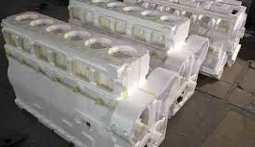
The grey cast iron used in this study, designated as HT200, has the chemical composition shown in Table 1. This composition ensures adequate mechanical properties and castability for the end caps. The end cap casting has dimensions of 120 mm × 240 mm × 240 mm, with a minimum wall thickness of 9 mm and a weight of 9.259 kg. The structure includes various features such as ribs and thick sections, which can influence solidification and defect formation.
| Element | Content (wt%) |
|---|---|
| C | 3.3–3.5 |
| Si | 1.9–2.3 |
| Mn | 0.6–0.8 |
| P | ≤0.30 |
| S | ≤0.12 |
For the gating system design, we considered three schemes: top pouring, middle pouring, and bottom pouring. In lost foam casting, the gating cross-sections are typically larger than in conventional casting due to the foam decomposition. The design is based on hydraulic formulas, with the ratio of cross-sectional areas for the ingate, runner, and sprue given by:
$$
\sum F_{\text{inner}} : \sum F_{\text{runner}} : \sum F_{\text{sprue}} = 1 : 1.2 : 1.4
$$
The total cross-sectional area of the ingates is calculated using:
$$
\sum F_{\text{inner}} = \frac{G}{0.31 \mu t \sqrt{H_p}}
$$
where $G$ is the mass of molten metal flowing through the ingates (kg), $\mu$ is the total flow loss coefficient, $t$ is the pouring time (s), and $H_p$ is the average static pressure head height (cm). The pouring time is estimated as:
$$
t = K_t \sqrt{G}
$$
where $K_t$ is a correction factor, taken as 0.85 for lost foam casting with vacuum. The calculated cross-sectional areas for each gating system are summarized in Table 2.
| Pouring Scheme | Ingate (mm²) | Runner (mm²) | Sprue (mm²) |
|---|---|---|---|
| Top Pouring | 7 × 24 | 9 × 24 | 24 × 24 |
| Bottom Pouring | 10 × 35 | 12 × 35 | 35 × 35 |
| Middle Pouring | 11 × 11 | 11 × 27 | 27 × 27 |
We employed ProCAST software for numerical simulation to analyze the filling and solidification processes. The model included the casting, gating system, and sand box. The mesh was generated with a size of 10 mm for the casting and gating, and 20 mm for the sand box. Key parameters set in the simulation included gravity direction, material properties, heat transfer coefficients, and boundary conditions. The foam pattern was made of EPS with a density of 22 kg/m³, thermal conductivity of 0.15 W/(m·K), specific heat of 3.7 kJ/(kg·K), latent heat of 100 kJ/kg, melting temperature of 350°C, and glass transition temperature of 330°C. The heat transfer coefficient between the casting and sand mold was set to 500 W/(m²·K), and between the foam and sand mold to 100 W/(m²·K). The pouring temperature was varied, and negative pressure was applied at specific locations.
The filling process for the top pouring scheme showed that metal flow was rapid due to the alignment with gravity, but it resulted in splashing and air entrainment. The total filling time was approximately 10.95 s, with each 30% fill stage taking about 3.7 s. The solidification process indicated that thin walls and ribs solidified first, while thick sections solidified last, taking 416.21 s for complete solidification. The gating system solidified before the top of the casting, leading to significant shrinkage cavities. For the middle pouring scheme, the filling time was 11.72 s, with four ingates causing turbulence and air entrainment. Solidification took 416.48 s, and shrinkage cavities formed at the top due to poor feeding. The bottom pouring scheme had a longer initial filling time of 6.20 s for the first 33%, but the overall filling was steady without splashing, taking 12.97 s. Solidification required 556.22 s, and the gating system provided effective feeding, minimizing defects.
To quantify the defects, we analyzed the porosity volume for each scheme. The top pouring had a porosity volume of 1.50 cm³, middle pouring had 2.38 cm³, and bottom pouring had 3.13 cm³. Although the bottom pouring had a slightly higher porosity volume, the defects were dispersed, and no significant shrinkage cavities were observed, making it the preferred scheme. The solidification time distributions further confirmed that the bottom pouring scheme allowed for better control over solidification, with the gating system remaining liquid longer to feed the casting.
We then conducted orthogonal experiments to optimize the pouring temperature and negative pressure for the bottom pouring scheme. The factors and levels are listed in Table 3. The experiments followed an L9 orthogonal array, and the porosity volume was measured for each combination. The results are presented in Table 4, and range analysis was performed to determine the influence of each factor, as shown in Table 5.
| Level | Factor A: Pouring Temperature (°C) | Factor B: Negative Pressure (MPa) |
|---|---|---|
| 1 | 1360 | 0.02 |
| 2 | 1390 | 0.04 |
| 3 | 1420 | 0.06 |
| Experiment No. | A: Pouring Temperature (°C) | B: Negative Pressure (MPa) | Porosity Volume (cm³) |
|---|---|---|---|
| 1 | 1360 | 0.02 | 4.728 |
| 2 | 1360 | 0.04 | 3.128 |
| 3 | 1360 | 0.06 | 2.930 |
| 4 | 1390 | 0.02 | 3.492 |
| 5 | 1390 | 0.04 | 3.128 |
| 6 | 1390 | 0.06 | 3.517 |
| 7 | 1420 | 0.02 | 3.321 |
| 8 | 1420 | 0.04 | 3.578 |
| 9 | 1420 | 0.06 | 3.005 |
| Factor | K1 | K2 | K3 | Range (R) |
|---|---|---|---|---|
| A: Pouring Temperature | 10.786 | 10.137 | 9.904 | 0.882 |
| B: Negative Pressure | 11.541 | 9.834 | 9.447 | 2.094 |
The range analysis indicated that negative pressure has a greater influence on porosity volume than pouring temperature, with ranges of 2.094 and 0.882, respectively. The optimal parameters were determined as a pouring temperature of 1420°C and a negative pressure of 0.06 MPa, which resulted in the smallest porosity volume of 3.005 cm³. Production verification under these conditions confirmed that the castings met the required microstructure and properties, with a process yield of 77.7%. The lost foam casting process, when properly designed and optimized, can significantly reduce defects and improve efficiency.
In conclusion, our study demonstrates the importance of gating design and process parameters in lost foam casting for grey cast iron end caps. The bottom pouring scheme proved superior to top and middle pouring in minimizing shrinkage defects. Through numerical simulation and orthogonal experiments, we optimized the pouring temperature and negative pressure, achieving a high-quality casting with minimal porosity. This approach can be extended to other iron castings, enhancing the applicability of lost foam casting in industrial production. Future work could focus on incorporating coating layer parameters in simulations to better reflect actual conditions, further improving the accuracy of lost foam casting models.
The lost foam casting process continues to evolve, and our research contributes to its advancement by providing a systematic methodology for design and optimization. By leveraging computer simulations and statistical methods, we can overcome the challenges associated with this technique, making it more reliable and efficient for complex castings. We hope that our findings will inspire further innovations in lost foam casting, ultimately leading to broader adoption in various sectors.