
In the field of coal mining machinery, the cutting roller of a shearer is a critical component responsible for coal extraction, fragmentation, and loading. During operation, the roller undergoes linear traction and rotational cutting motions. The blades equipped with pick-shaped cutters are in direct and continuous contact with coal and rock strata, subjecting them to severe abrasive wear, making them highly vulnerable to damage. Traditionally, these blades are fabricated from low-carbon steel to ensure good weldability, but this material offers poor wear resistance. To protect the blades and extend their service life, wear-resistant blocks are welded onto the blade edges. Conventional wear-resistant blocks are made from single-material medium-carbon medium-alloy steel, typically with a composition of 0.42%–0.46% C, 0.30%–0.80% Si, 0.60%–0.70% Mn, 1.20%–2.00% Cr, 0.70%–0.80% Ni, 0.15%–0.20% Mo, and P, S ≤ 0.04%, achieving a hardness of HRC 40–43. While somewhat wear-resistant, these blocks exhibit poor weldability, often leading to detachment during service. To address this, we have developed a bimetal wear-resistant block using the lost foam casting process, which combines a low-carbon steel non-working layer for weldability and a high-chromium iron working layer for superior wear resistance. This article details our comprehensive study from design to implementation, emphasizing the advantages of the lost foam casting process.
The core innovation lies in the integration of two distinct metals via a solid-liquid bonding approach facilitated by the lost foam casting process. The bimetal block consists of a non-working layer (welding layer) made from low-carbon alloy steel plate and a working layer made from high-chromium cast iron. The dimensions of the final block are 80 mm × 100 mm × 20 mm. The non-working layer, with a thickness of 8 mm, is machined from a commercial low-carbon steel plate to ensure excellent weldability to the shearer blade. The working layer, with a thickness of 12 mm, is designed for maximal abrasion resistance. The bonding is achieved by attaching the machined steel plate to a foam pattern of the working layer. During casting, molten high-chromium iron fills the mold, and upon contact with the solid steel plate, a thin interfacial layer melts and fuses with the iron, creating a metallurgical bond. To enhance this bond’s strength, we designed conical connection holes in the steel plate. Initial designs used small trapezoidal holes, which led to stress concentration and fracture at the interface during hammer impact tests. The optimized design features larger conical holes with an outer diameter of Φ20 mm and an inner diameter of Φ16 mm. This geometry promotes complete metal filling, reduces stress risers, and significantly improves bond integrity, as confirmed by subsequent destructive testing showing no separation.
The success of the lost foam casting process hinges on meticulous pattern production. We manually cut expandable polystyrene (EPS) foam with a density of 0.016–0.018 g/cm³ using a hot wire to create precise patterns for the working layer. The pattern’s dimensional accuracy is critical, incorporating a shrinkage allowance of 1.02%. The foam pattern must have a smooth surface, good bead fusion, and no significant protrusions or depressions. Before assembly, the steel plate undergoes surface cleaning to remove contaminants. The plate and foam pattern are joined using white glue, with foam plugs inserted into the conical holes to prevent sand intrusion during molding. Any gaps at the joint are sealed with paper strips. The assembled pattern is then dried for 24–48 hours at 52 °C ± 3 °C in an infrared drying chamber to eliminate moisture and prevent deformation, as residual water can cause defects like gas pores or mold collapse during pouring.
Coating application is another vital step in the lost foam casting process. A high-quality refractory coating enhances pattern strength, prevents sand burning, and improves surface finish. We formulated a water-based coating using 53 μm quartz flour as the refractory aggregate, white glue as the binder, cellulose as the suspending agent, and water as the solvent. The mixture is ball-milled for 4–6 hours to ensure homogeneity. The dried pattern is manually coated with three layers of this slurry. Each layer is dried completely in the infrared chamber before the next is applied. This builds a robust, gas-permeable barrier that withstands the thermal and mechanical stresses of molding and pouring.
The gating system design within the lost foam casting process directly influences casting yield and quality. We initially tested an end-to-end串联式 single-layer gating system, where multiple patterns were connected in series to a single runner. This led to insufficient filling at the distal ends, resulting in misrun defects and low yield. Furthermore, the interconnected runners were difficult to clean, increasing the risk of damaging the cast blocks during knockout. We then developed a split-type upper and lower double-layer gating system. This system features a central downsprue that branches symmetrically to feed two layers of patterns arranged in a staggered layout. This design ensures balanced metal flow and uniform filling for all cavities, achieving a near 100% casting yield. The molding process employs a bottom-vacuum flask measuring 1350 mm × 1000 mm × 500 mm. Dry silica sand with a grain size of 850–425 μm is used. The procedure involves: (1) placing a 100 mm base layer of sand in the flask and compacting it by vibration; (2) positioning the first layer of coated patterns, ensuring no “bare” spots are exposed, and sealing any joints with refractory clay; (3) filling sand using a rain-like method from the sides to avoid pattern damage, vibrating for 1 minute after filling, with a top sand cover of 100 mm; (4) repeating for the second layer; (5) covering the flask with a plastic film and adding a 100 mm sand layer atop the film to protect it from molten metal splash during pouring.
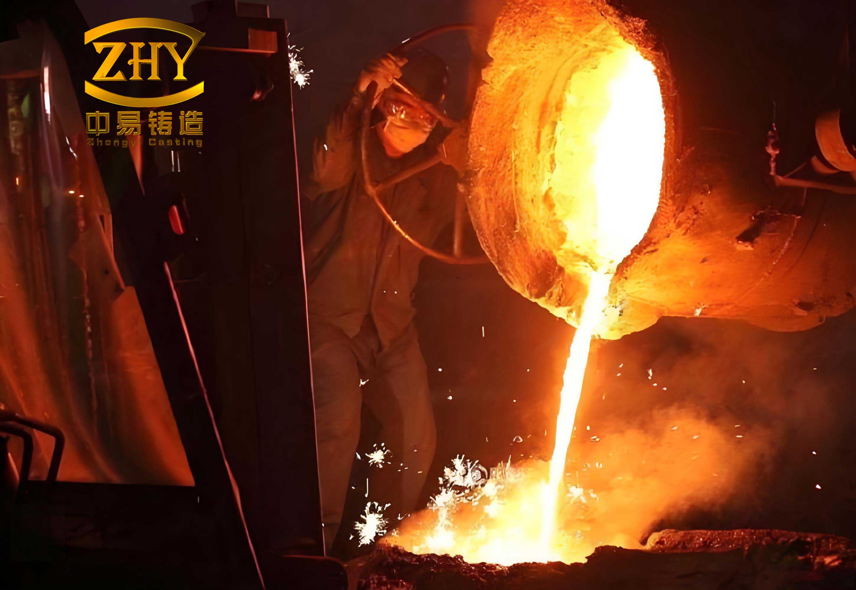
Melting and pouring parameters are crucial for the lost foam casting process. The high-chromium iron for the working layer is melted in a 250 kg medium-frequency induction furnace. The charge calculation is based on the target composition: 2.6%–3.3% C, 0.3%–0.8% Si, 1.4%–2.0% Mn, 17%–20% Cr, with P and S limited to ≤0.04%. The furnace is charged densely and powered initially at low power for 6–8 minutes to avoid current surge, then gradually increased to maximum. Bridging is prevented by frequent charge pushing. When the charge is fully molten and the temperature reaches 1480 °C, the melt is tapped into a preheated ladle (>600 °C). The vacuum system (a SK-12 water-ring pump) is activated, setting a negative pressure of -0.06 to -0.035 MPa. After slag removal and a 2–3 minute镇静 period, when the metal temperature drops to 1420 °C, pouring commences. The negative pressure is maintained during pouring and then adjusted to -0.025 MPa for 15 minutes after pouring to solidify the casting under reduced pressure. The castings are left in the sand for 8 hours of insulation before shakeout and air cooling.
Heat treatment is essential to achieve the desired microstructure and mechanical properties in the high-chromium iron layer. The bimetal blocks undergo a normalizing and tempering process. The normalizing involves heating to 980 °C, holding for 2 hours, followed by air cooling. Subsequently, tempering is performed at 250 °C for 4 hours, followed by air cooling. This treatment aims to transform the as-cast structure into a hardened matrix with tempered martensite, enhancing both hardness and toughness.
The interfacial bonding quality was evaluated macroscopically by sectioning a block with a wire-cut electrical discharge machine. The cross-section revealed a clear, defect-free interface between the steel plate and the high-chromium iron, with no visible pores, cracks, or delamination. Hammer impact tests repeatedly applied to the interface caused no separation, confirming a robust metallurgical bond achieved through the lost foam casting process.
Microstructural analysis was conducted on samples extracted from the heat-treated working layer. The specimens were ground, polished, and etched with 4% nital solution. Observation under an optical microscope revealed the microstructure comprising tempered martensite matrix, eutectic carbides, and a small amount of retained austenite. The carbides exhibited various morphologies: predominantly nodular and blocky, with some elongated types. This microstructure is responsible for the high wear resistance. The hardness and impact toughness were measured systematically. The average surface hardness (HRC) and impact energy are summarized below.
| Sample | Hardness Test Points (HRC) | Average Hardness (HRC) | Impact Energy (J) | Average Impact Energy (J) |
|---|---|---|---|---|
| 1 | 60.5, 61.5, 61.0 | 61.0 | 6.5 | 6.6 |
| 2 | 61.0, 61.0, 60.5 | 60.8 | 6.8 | |
| 3 | 61.5, 61.0, 61.5 | 61.3 | 6.5 |
The overall average hardness is calculated as approximately HRC 61, and the average impact toughness is 6.6 J. These values represent a significant improvement over the traditional single-material blocks (HRC 40-43). The relationship between hardness and wear resistance can be conceptually framed, although wear involves multiple factors. The volume fraction of hard carbides is a key contributor. We can estimate the carbide volume fraction \( V_c \) using a simplified rule of mixtures based on composition, though precise measurement requires image analysis. The high chromium content promotes the formation of (Cr, Fe)7C3 carbides, which are exceptionally hard. The hardness of the martensitic matrix, \( H_m \), and carbides, \( H_c \), combine to give the composite hardness \( H \):
$$ H \approx V_c \cdot H_c + (1 – V_c) \cdot H_m $$
Where \( H_c \) can exceed 1500 HV and \( H_m \) after tempering is around 600-700 HV. For our composition with ~20% Cr and ~3% C, \( V_c \) is substantial, leading to high overall hardness.
The lost foam casting process parameters directly affect the soundness of the casting. The filling velocity \( v \) in the mold is influenced by the pressure difference \( \Delta P \) between the atmosphere and the flask vacuum, the density of the metal \( \rho \), and the geometry of the gating system. A simplified Bernoulli-based equation for fluid flow in a vacuum-assisted lost foam process can be expressed as:
$$ v \propto \sqrt{\frac{2 \Delta P}{\rho} + 2gh} $$
where \( g \) is acceleration due to gravity and \( h \) is the effective metallostatic head. Our split gating system ensures minimal flow resistance and balanced \( h \) for all cavities, promoting simultaneous filling.
The solidification behavior is critical for bond formation. The heat transfer at the bimetal interface involves the liquid high-chromium iron at temperature \( T_{pour} \) (1420 °C) contacting the solid steel plate at initial temperature \( T_{room} \). The interfacial heat flux \( q \) drives melting of a thin steel layer and subsequent interdiffusion. The thickness of the melted layer \( \delta \) can be approximated by:
$$ \delta \sim \sqrt{\alpha_{steel} \cdot t_{contact}} $$
where \( \alpha_{steel} \) is the thermal diffusivity of steel and \( t_{contact} \) is the time during which the iron remains liquid at the interface. The conical holes increase the contact area and turbulence, enhancing this thermal and mass exchange.
To further quantify the process efficiency, we compared key parameters between the initial and optimized lost foam casting process setups.
| Process Aspect | Initial Design (Trapezoidal Holes, Series Gating) | Optimized Design (Conical Holes, Split Double-Layer Gating) |
|---|---|---|
| Bonding Hole Geometry | Trapezoidal, small (Φ12/Φ8 mm) | Conical, large (Φ20/Φ16 mm) |
| Gating System | End-to-end series, single layer | Split symmetrical, double layer |
| Casting Yield | ~70% (due to misruns) | ~100% |
| Interfacial Bond Strength | Low (fracture at holes in impact test) | High (no fracture in impact test) |
| Production Efficiency (Blocks per flask) | Limited by single-layer layout | Doubled via double-layer layout |
| Pattern Complexity | Moderate | Moderate (added hole machining) |
The final validation came from field trials. The bimetal wear-resistant blocks produced via the optimized lost foam casting process were installed on shearer cutting rollers for in-service evaluation. Under continuous operation without failure or maintenance, the new blocks achieved a service life of 523 hours. In contrast, the traditional single-material alloy steel blocks lasted only 375 hours on average under similar conditions, and instances of block detachment were recorded. This represents a service life improvement of approximately 39%. The enhanced performance is attributed to the synergistic combination of the tough, weldable steel backing and the extremely hard, wear-resistant high-chromium iron working layer, seamlessly integrated by the lost foam casting process.
In conclusion, our research demonstrates the significant advantages of employing the lost foam casting process for manufacturing bimetal wear-resistant blocks. The solid-liquid bonding mechanism, facilitated by careful design of interfacial features like conical holes, produces a robust metallurgical joint. The optimized gating system within the lost foam casting process ensures high casting yield and production efficiency. The resultant microstructure after tailored heat treatment provides superior hardness (HRC ~61) and adequate impact toughness (6.6 J). Field performance confirms a substantial extension in service life compared to conventional blocks. The lost foam casting process proves to be a highly effective and reliable method for producing complex composite castings where dissimilar material properties are required in different zones of a component. Future work could focus on further refining the alloy compositions, exploring automated pattern manufacturing, and modeling the thermal-stress evolution during solidification of such bimetal systems within the lost foam casting process to optimize the interface properties further.