
The production of critical conductive components for high-speed electric locomotives presents a formidable challenge to any foundry. Our facility recently undertook the manufacturing of a batch of brush holders for a foreign rail current grounding system. The design demanded a component that ensures precise brush retention, smooth sliding motion, and uninterrupted electrical conductivity. Consequently, the material specification called for high-strength, high-conductivity aluminum bronze (approximate composition: Cu ~84%, Al ~9.5%, Fe ~3.5%, Ni ~2.5%). The quality requirements were exceptionally stringent: a surface roughness better than Ra 3.2 μm, and the complete absence of surface and internal defects such as porosity, sand inclusion, or slag. Furthermore, machined surfaces were also required to be defect-free, and the castings were subject to radiographic (X-ray) inspection for internal soundness.
Analysis of the provided drawings and sample revealed a part of complex geometry with high dimensional accuracy requirements, making it a difficult candidate for conventional casting. The basic configuration consists of a flange integrated with an irregularly shaped cylindrical body. The flange incorporates protruding blocks serving as current terminals, while the cylinder houses three independent, uniformly spaced brush pockets. The wall thickness is highly variable, ranging from a mere 4 mm in thin sections to 18 mm in thick sections. Given that aluminum bronze is an alloy prone to significant shrinkage, oxidation, and gas absorption, the thin sections were susceptible to cold shuts and slag entrapment, and the thick sections were likely sites for shrinkage porosity. To successfully produce a sound casting, the key challenges to address were: the pouring position, the design of the gating system, and effective slag removal and feeding. After careful evaluation, the lost wax investment casting process was selected, specifically utilizing a silica sol binder system, combined with a shower gate (rain gate) system and strategic risers for feeding.
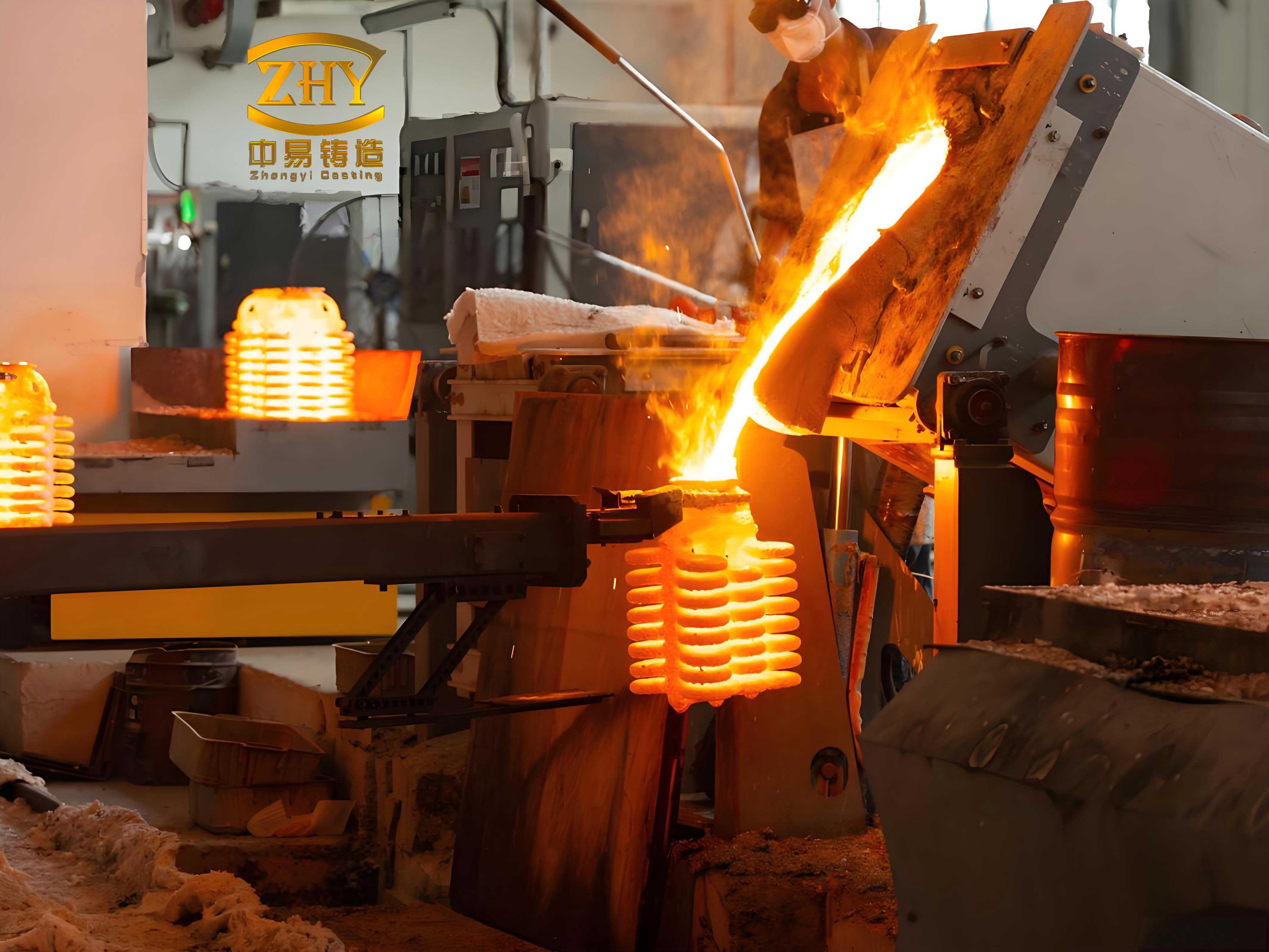
The fundamental advantage of lost wax investment casting lies in its ability to produce net-shape or near-net-shape components with excellent surface finish and dimensional accuracy from almost any alloy. The process begins with an expendable wax pattern, around which a ceramic shell is built layer-by-layer. Once the shell is hardened and the wax melted out, it forms a precise, single-use mold ready for metal pouring. For this intricate aluminum bronze part, this method offered the best chance of success.
Pattern Assembly and Gating System Design
The heart of successful lost wax investment casting is a robust process design that accounts for fluid flow, solidification, and feeding. For this brush holder, a horizontal pouring arrangement was chosen. The gating system was designed as a combined “shower” and riser system to achieve controlled, tranquil filling and directional solidification.
The core concept is illustrated in the process layout. The sprue terminates into three choke sprues, which act as flow controllers, increasing flow resistance and reducing metal stream turbulence and impingement. The metal then enters a larger cross-section runner, where its velocity decreases further. From the runner, the metal flows through multiple small-diameter “shower gates” (rain gates) that open into the tops of three risers and the mold cavity itself. This design offers the dual benefits of a pressurized system (good slag trapping) and an open system (steady filling), promoting a bottom-up filling sequence. This ensures that air and oxides are pushed ahead of the metal front toward the top of the mold. The risers are positioned directly over the thickest sections of the flange, providing a reservoir of hot metal to compensate for solidification shrinkage, thereby creating the essential conditions for directional solidification—from the thin sections of the cylinder toward the risers.
The proportions of the gating system elements were carefully calculated as follows:
$$ \text{Sprue Area} : \text{Choke Sprue Total Area} : \text{Runner Area} : \text{Ingate Total Area} = 1.0 : 0.8 : 1.2 : 1.1 $$
The riser dimensions were designed to be 120 mm (L) × 40 mm (W) × 60 mm (H). The fill time \( t_f \) can be estimated using the Bernoulli and continuity equations, considering the effective head \( h \) and the total ingate area \( A_i \):
$$ t_f \approx \frac{V_{cavity}}{A_i \cdot v_i} = \frac{V_{cavity}}{A_i \cdot \mu \cdot \sqrt{2 g h}} $$
where \( V_{cavity} \) is the volume of the mold cavity, \( v_i \) is the velocity at the ingates, \( \mu \) is the discharge coefficient (≈0.8 for ceramic shells), and \( g \) is gravitational acceleration. This calculation ensured the fill time was sufficiently fast to avoid cold shuts in thin sections but not so turbulent as to cause oxide entrainment.
Pattern Die Design and Wax Pattern Production
The success of the lost wax investment casting process is fundamentally tied to the quality and precision of the wax pattern. The first step was the design and manufacture of the pattern die (mold).
Design Parameter Selection:
• Machining Allowance: Upper surfaces: 2.5 mm, Lower surfaces: 1.5 mm, Brush pocket inner walls: 0.5 mm (minimal).
• Pattern Shrinkage Allowance: This must account for wax contraction, shell expansion, and metal contraction. The total linear shrinkage \( \epsilon_t \) was determined as:
$$ \epsilon_t = \epsilon_w + \epsilon_s + \epsilon_m $$
For this aluminum bronze alloy and silica sol shell system, the following were applied:
• Free Contraction (External dimensions): 1.8%
• Restricted Contraction (Internal dimensions, cores): 1.2%
• Height Contraction: 1.5%
Die Structure and Core Design:
The parting line was set on the upper plane of the flange for easy pattern ejection. The internal step on the flange was formed by a corresponding step in the upper die half. The three brush pockets and the internal cavity were created by a single, retractable “flower” core pin assembly that passed through both die halves. The wax injection point was located on one of the terminal blocks. The die incorporated alignment pins for angular positioning and matching boss/rebate features for coaxial alignment. The wax injection sprue was designed to directly form the wax version of the riser on the terminal block.
Wax Pattern Production:
A wax-based pattern material was used with the following composition and process parameters.
| Parameter | Value / Specification |
|---|---|
| Wax Composition (Ratio) | Paraffin Wax : Stearic Acid = 50 : 50 |
| Melting Temperature | 68 – 72 °C |
| Injection Temperature | 48 – 52 °C |
| Injection Pressure | 0.4 – 0.6 MPa |
| Die Temperature | 22 – 25 °C |
| Pressure Holding Time | 30 – 60 s |
| Cooling Time before Ejection | 90 – 180 s |
| Parting Agent | Transformer Oil or Turpentine |
The procedure involved cleaning and coating the die with release agent, assembling and clamping it, followed by wax injection. The ejected wax patterns were briefly cooled in water and then air-dried on racks. Individual wax patterns were then assembled onto a central wax gating system (sprue, runner, risers) using heated tools and wax welds to create a cluster (tree). The assembled cluster was cleaned in a mild detergent solution to remove contaminants and grease, then dried thoroughly before proceeding to shell building.
Ceramic Shell Building with Silica Sol Binder
The lost wax investment casting shell is the negative of the final part and must possess adequate strength, permeability, and thermal stability. We employed a silica sol binder system, which relies on drying to induce gelation and hardening.
Slurry Preparation: The properties of the primary (face coat) and secondary (back-up coat) slurries are critical.
| Component / Property | Primary Slurry | Secondary Slurry |
|---|---|---|
| Binder: Silica Sol (SiO₂) | 30 – 33% (by weight) | 25 – 28% |
| Refractory: Zircon Flour | ~200 mesh (approx. 75 μm) | – |
| Refractory: Molochite (or similar) | – | Various grades |
| Wetting Agent | 0.1 – 0.3% | 0.05 – 0.1% |
| Anti-foam Agent | as required | as required |
| Slurry Density | 1.75 – 1.85 g/cm³ | 1.70 – 1.80 g/cm³ |
| Slurry Viscosity (Ford Cup #4) | 28 – 32 s | 22 – 26 s |
Shell Building Process: The process follows a repetitive cycle: Dip → Drain → Stucco → Dry. The specific parameters for our multi-layered shell are summarized below.
| Layer Sequence | Slurry Type | Stucco Sand (Grade) | Drying Condition (Temp., RH, Time) |
|---|---|---|---|
| 1st (Prime Coat) | Primary (Zircon) | Zircon (100-200 mesh) | 22-25°C, 50-70% RH, 8-12 h |
| 2nd | Secondary | Molochite (A-80) | 22-25°C, 50-70% RH, 6-8 h |
| 3rd | Secondary | Molochite (A-30) | 22-25°C, 50-70% RH, 6-8 h |
| 4th to 7th | Secondary | Molochite (A-16 or coarse) | 22-25°C, 50-70% RH, 4-6 h each |
After the final layer dried, the completed shell cluster was aged for a minimum of 24 hours to ensure complete gelation and strength development.
Dewaxing and Firing: Dewaxing was performed in a high-pressure steam autoclave at 150-160°C and 0.6-0.8 MPa pressure, typically completing within 3-5 minutes. This rapid wax removal minimizes shell cracking. The dewaxed shells were then fired in an electric resistance furnace to eliminate residual wax, volatiles, and moisture, and to develop final shell strength. The firing cycle was: Heat to 950-1000°C, hold for 2 hours to ensure thermal soak, then cool slightly. Shells were preferably cast while still hot from the furnace to prevent moisture reabsorption.
Alloy Melting, Pouring, and Process Control
Aluminum bronze requires meticulous melting practice due to its tendency to oxidize (form Al₂O₃ dross) and absorb hydrogen gas, which leads to subsurface pinhole porosity.
Melting Practice: A medium-frequency induction furnace with a pre-sintered magnesia crucible was used. The charge sequence and practice were as follows:
1. Pre-heat crucible to dull red heat (~600°C).
2. Add a thin layer of covering flux (60% glass cullet + 40% soda ash), approximately 0.5% of charge weight.
3. Charge materials: Start with electrolytic copper (85% of total), followed by pre-mixed master alloys or pure metals: metallic manganese, nickel, low-carbon steel punchings, and finally aluminum (with ~15% of Cu and Al held back for final adjustment). Add recycled gates/risers of the same specification. Add another 0.5% cover flux after a molten pool forms.
4. Melt rapidly under a slightly oxidizing atmosphere to minimize hydrogen pickup, with gentle stirring.
5. After full melt-down at 1180-1200°C, add the remaining Cu and Al for temperature and composition fine-tuning. Add a refining flux (e.g., a mixture of cryolite, NaCl, and potassium fluoride) at 0.3-0.5% of charge weight.
6. Perform quality tests:
• Reduced Pressure Test: A sample is solidified under partial vacuum. Extensive bubble formation indicates high gas (H₂) content.
• Bend Test: A test bar is bent; a brittle fracture with a crystalline appearance may indicate excessive oxides or incorrect microstructure.
7. If the gas test fails, degas using dehydrated zinc oxide (0.1-0.15% of charge weight) which decomposes to release ZnO vapor, promoting hydrogen bubble coalescence and removal: $$ \text{ZnO (s)} + \text{H (in melt)} \rightarrow \text{Zn (g)} + \text{OH (bubble)} $$
8. Upon passing the tests, skim off dross, cover the melt with a thin layer of cryolite to protect it, and prepare for pouring.
Pouring Practice: The shell temperature at pouring was maintained at 800-900°C. The superheated alloy was tapped into a pre-heated ladle, allowed to settle for about 1 minute to let inclusions float, and then poured. The pouring temperature was tightly controlled between 1120-1150°C. The pouring technique was “quick start, slow finish” to maintain a non-turbulent fill without interruption. Observation of the riser behavior post-pouring was a critical qualitative check:
• Concave shrinkage in the riser indicated good feeding and low gas content.
• Riser swelling or “boiling” indicated high dissolved gas content, foretelling porosity in the casting.
Quality Verification and Process Outcomes
The efficacy of the developed lost wax investment casting process was validated through rigorous inspection.
Chemical Composition: Spectrographic analysis confirmed the alloy met the required specifications (Cu-balance, Al~9.5%, Fe~3.5%, Ni~2.5%, Mn<1%).
Mechanical Properties: Test coupons cast alongside the production clusters showed:
• Tensile Strength (σ_b): ≥620 MPa
• Elongation (δ): ≥12%
• Hardness (HB): 130-150
Non-Destructive Testing (NDT): A 100% visual inspection was performed. Additionally, a 10% sampling rate was subjected to industrial X-ray radiography. No shrinkage porosity, gas pores, or non-metallic inclusions were detected in the critical sections of the sampled castings. The surface finish was measured and found to be better than Ra 3.2 μm, exceeding the requirement.
The successful production of this complex aluminum bronze brush holder demonstrates the powerful synergy of process design and metallurgical control within the lost wax investment casting framework. Key conclusions are:
- The silica sol shell process provides the necessary strength and surface finish for precision castings.
- The shower-type gating system combined with strategic risers is highly effective for complex, thin-thick walled parts, ensuring tranquil filling and promoting directional solidification to eliminate shrinkage defects.
- For reactive alloys like aluminum bronze, rigorous melt protection, effective degassing/refining, and precise temperature control are non-negotiable prerequisites for achieving sound, dense castings.
The lost wax investment casting process, when engineered with such detailed attention to pattern, shell, gating, and metallurgy, is capable of producing near-net-shape components of exceptional integrity and performance, even for demanding applications in the transportation and electrical industries. The process flexibility allows for optimization via mathematical modeling of fluid flow and solidification, where key parameters like modulus \( M = \frac{V}{A} \) (Volume/Surface Area) of casting sections and risers guide feeding design, and Chvorinov’s Rule governs solidification time: $$ t_s = B \cdot \left( \frac{V}{A} \right)^n = B \cdot M^n $$ where \( B \) is the mold constant and \( n \) is typically ~2. This scientific approach underpins the repeatable success of modern lost wax investment casting.