
As a researcher deeply involved in the study of lost foam casting processes, I have observed that inclusion defects are a pervasive and challenging issue, particularly for novice foundries adopting this technique. These defects significantly compromise the mechanical properties, machinability, and overall integrity of castings, often leading to premature failure in service. This article, from my perspective, delves into the intricate formation process of inclusion defects in lost foam casting, analyzes the underlying conditions, and proposes practical pathways for mitigation. I will structure the discussion around the morphology of defects, the unique metal filling dynamics in lost foam casting, the sources of inclusions, and finally, the strategies to minimize their occurrence. Throughout, I will emphasize the role of process parameters and employ tables and mathematical formulations to summarize key concepts, ensuring the keyword ‘lost foam casting’ is frequently highlighted to maintain focus.
In lost foam casting, the casting is formed by pouring molten metal into a mold containing a foam pattern that vaporizes upon contact. This process offers advantages like design flexibility and reduced machining, but it is inherently prone to defects such as inclusions, slag holes, and gas porosity, often intertwined. These defects typically manifest as irregular, clustered formations within the casting, with varying colors and compositions indicating their origin—be it coating debris, pyrolysis residues from the foam, or metallurgical slag. A common observation is their propensity to appear near the top surfaces, beneath the skin layer (around 2–30 mm deep), and at junctions with gating systems. This distribution is not random but is closely tied to the turbulent flow dynamics and solidification sequence inherent to the lost foam casting process under vacuum conditions.
| Defect Type | Morphology & Appearance | Typical Composition | Common Locations in Casting |
|---|---|---|---|
| Coating/Sand Inclusions | Irregular clusters, often with sharp edges; white or grayish powder or distinct sand grains. | Detached coating fragments, sand particles from mold intrusion. | Top surfaces, near gating junctions, subsurface regions. |
| Slag Inclusions | Dark gray to black irregular masses, sometimes porous. | Oxides, refining slag, foam pyrolysis carbonaceous residues. | Throughout, but often concentrated in upper sections and slow-flow areas. |
| Gas-Slag Porosity | Combined cavities containing both gas and solid/liquid inclusions. | Entrapped gases (pyrolysis, dissolved) mixed with slag particles. | Hot spots, thick sections, areas with poor gas evacuation. |
| Pattern Adhesive Residue | Localized defects along seam lines. | Un-vaporized or partially decomposed adhesive. | Pattern assembly seams. |
The formation of these defects is intrinsically linked to the metal filling process in lost foam casting, which is radically different from conventional empty-mold casting. My investigations, alongside studies from various institutions, reveal that the filling morphology is governed by the interplay of metal flow, foam decomposition, and crucially, the applied vacuum. In the absence of vacuum, for alloys like aluminum, the metal front can advance in distinct modes: contact, gap, collapse, and entrainment. However, in the lost foam casting of ferrous alloys widely practiced in industry, vacuum application is standard to ensure mold rigidity. This vacuum drastically alters the flow regime.
Under vacuum, the metal filling becomes highly turbulent. The pressure differential accelerates the metal flow, but it also induces a strong “wall-attachment” effect. This effect causes the molten metal to preferentially flow along the coating-mold wall, creating a fast-advancing, thin solidified shell at the periphery while the central core fills more slowly. This results in a U-shaped filling front. The mathematical representation of the pressure in the gap between the metal and the decomposing foam is critical. Based on experimental data, the gap pressure $P_{gap}$ can be expressed as:
$$ P_{gap} = P_{atm} – \Delta P_{vacuum} + \Delta P_{pyrolysis} $$
where $P_{atm}$ is atmospheric pressure, $\Delta P_{vacuum}$ is the applied vacuum pressure (typically 0.02-0.04 MPa in practice), and $\Delta P_{pyrolysis}$ is the transient pressure increase due to gaseous foam decomposition products. During filling, $P_{gap}$ can range from approximately 0.096 MPa to 0.12 MPa depending on process conditions. This pressure resists metal advancement and influences bubble formation. The local metal velocity $v$ near the wall can be significantly higher than in the center. A simplified model for the wall-attachment velocity enhancement can be derived from a balance of pressure and viscous forces:
$$ v_{wall} \approx \sqrt{\frac{2 \Delta P_{vacuum}}{\rho}} + C \cdot \frac{\mu}{\rho \delta} $$
where $\rho$ is metal density, $\mu$ is dynamic viscosity, $\delta$ is the gap thickness, and $C$ is a constant. This turbulent, wall-hugging flow creates vortices and recirculation zones that readily entrap non-metallic inclusions and gases, carrying them into the casting body instead of allowing them to float out.
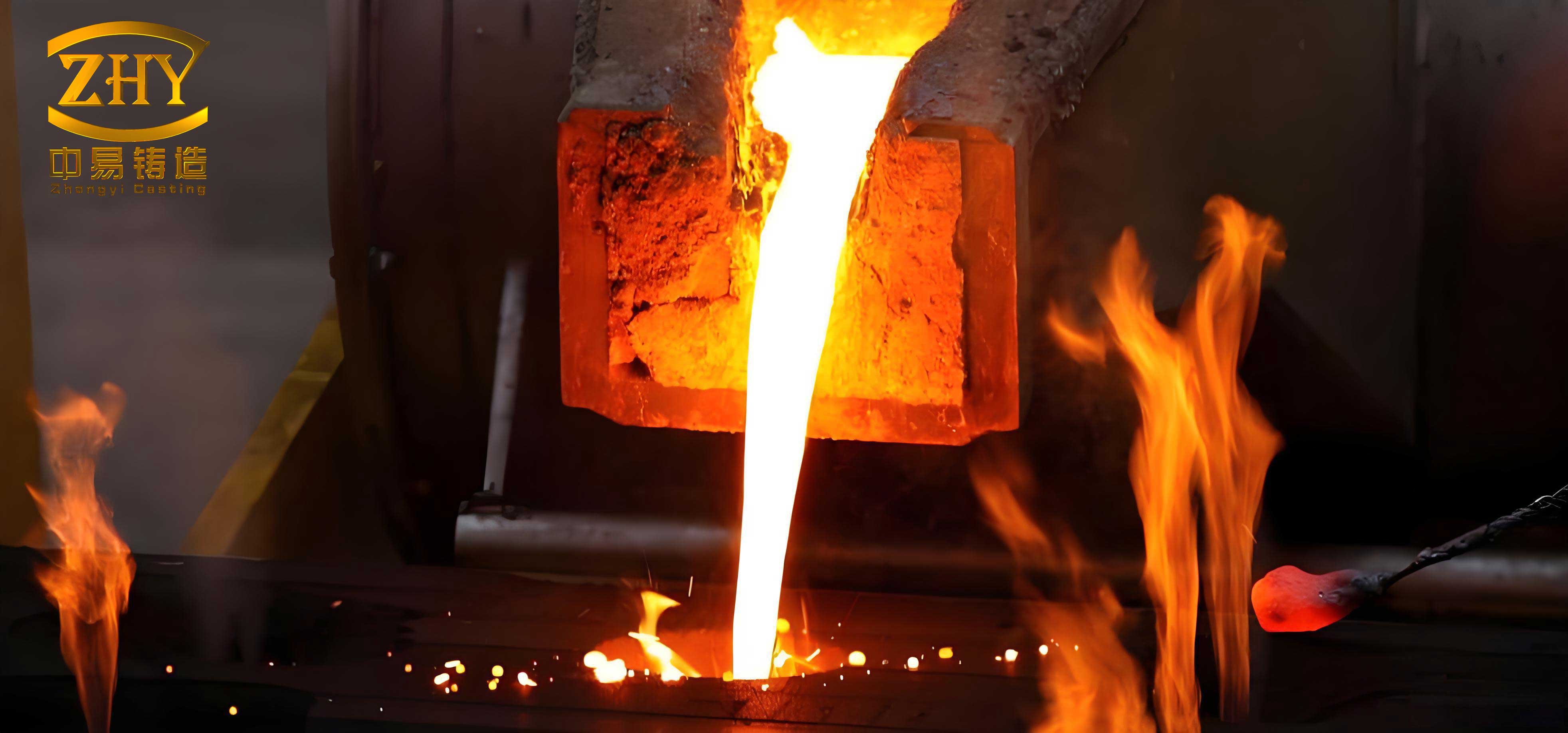
The visualization above conceptually represents the complex interaction during the lost foam casting process. The turbulent flow and the evolving gap are key to understanding defect genesis. The sources of inclusions in the metal bath during lost foam casting are multifaceted. They can be categorized as endogenous (originating from the metal itself) and exogenous (introduced from the mold or pattern).
| Source Category | Specific Origin | Nature of Inclusions | Relative Contribution (Typical) |
|---|---|---|---|
| Endogenous | Melting Process (e.g., using scrap steel) | Oxides, slag, impurities (S, P inclusions), dissolved gases. | High (Primary Contributor) |
| In-mold Reactions (metal oxidation) | Secondary oxides formed during pouring. | Medium | |
| Exogenous | Foam Pattern Pyrolysis | Carbonaceous residues, liquid polymer droplets. | Low to Medium (Depends on foam density) |
| Coating Detachment | Crushed coating pieces, especially from rough pattern surfaces. | Medium (Major issue with cut foam patterns) | |
| Mold Intrusion (Sand) | Silica sand grains entering due to poor sealing. | Low to High (Process-dependent) | |
| Process-Related | Pattern Adhesive | High-density, incomplete vaporization residues. | Medium (Scaled with seam length) |
The dynamics of inclusion movement and entrapment are governed by Stokes’ law and the turbulent flow field. The terminal floating velocity $v_f$ of a spherical inclusion in a quiet melt is given by:
$$ v_f = \frac{2 g r^2 (\rho_m – \rho_i)}{9 \mu} $$
where $g$ is gravity, $r$ is inclusion radius, $\rho_m$ and $\rho_i$ are densities of metal and inclusion, respectively. In the turbulent lost foam casting environment, this velocity is often overwhelmed by the fluctuating velocity components $v’_{x,y,z}$ of the eddies. The probability of an inclusion being captured by the solidifying front, $P_{capture}$, increases with local solidification rate $R$ and inclusion size, and decreases with floating velocity. A simplified capture criterion can be expressed as:
$$ P_{capture} \propto \frac{R \cdot r}{v_f + |\vec{v}_{turbulent}|} $$
The negative pressure gradient in the mold (from vacuum ports typically on the sides/bottom) further complicates this. It creates a lateral pressure field that can draw inclusions sideways towards the mold walls, where the rapidly solidifying thin layer may trap them in the subsurface region. This explains the frequent observation of inclusion bands 2-30 mm below the casting surface. In contrast, a top-draft vacuum system would create a more favorable upward pressure gradient, aiding inclusion flotation, but this is less common in production.
Based on my experience and analysis, mitigating inclusion defects in lost foam casting requires a multi-pronged approach targeting both the reduction of inclusion sources and the modification of process conditions to enhance their removal.
1. Reducing Primary Inclusions in the Melt: This is the most effective strategy. Employing melt purification agents (fluxes) that agglomerate fine inclusions can be highly beneficial. The agglomeration efficiency $\eta_{agg}$ can be modeled as a function of agent concentration $C_a$ and temperature $T$:
$$ \eta_{agg} = k_1 C_a e^{-E_a / (RT)} $$
where $k_1$ is a constant, $E_a$ is activation energy, and $R$ is the gas constant. Using ceramic filters in the gating system is another direct method. The filtration efficiency for particles larger than the filter pore size $d_p$ is near 100%. Furthermore, using low-density expanded polystyrene (EPS) foam patterns (typically 16-24 kg/m³) minimizes the mass of pyrolysis residue, directly reducing one source of endogenous inclusions.
2. Optimizing Process Parameters & Gating Design: The gating system should be designed to minimize metal travel distance and turbulence. Avoiding multi-casting arrangements in a single flask reduces the length of runners where metal cools, oxidizes, and picks up inclusions. The most significant parameter is the vacuum level. While necessary for mold stability, it should be minimized. The optimal vacuum pressure $\Delta P_{opt}$ is the minimum that prevents mold collapse, which can be estimated from the sand cohesion and metal head pressure:
$$ \Delta P_{opt} \ge \rho_s g H_s + \frac{\rho_m g H_m}{K} – \sigma_{sand} $$
where $\rho_s$ and $H_s$ are sand density and height, $\rho_m$ and $H_m$ are metal density and effective head, $K$ is a permeability factor, and $\sigma_{sand}$ is sand cohesive strength. Lowering vacuum from, say, 0.04 MPa to 0.025 MPa can dramatically reduce turbulence and the wall-attachment effect, promoting a more quiescent filling front that allows inclusions to float towards the cope.
| Strategy Category | Specific Action | Mechanism of Action | Expected Impact |
|---|---|---|---|
| Melt Treatment | Use of refining fluxes/degassers. | Agglomeration and removal of oxides/slag; reduction of dissolved gas. | High reduction in endogenous inclusions. |
| Pattern Quality | Use of molded (not cut) foam patterns; sealing surface pores. | Eliminates coating penetration into cracks, preventing “coating nails.” | Eliminates major source of exogenous coating inclusions. |
| Coating & Sealing | Uniform, crack-free coating; rigorous sealing of sprue top with paste/film. | Prevents sand intrusion and coating spalling under metal flow. | Prevents sand and large coating inclusions. |
| Process Control | Minimizing vacuum to necessary level; optimizing pouring temperature. | Reduces turbulent entrainment; improves foam vaporization completeness. | Reduces entrapment of all inclusion types. |
| Gating Design | Short, direct gating; use of filters; top vacuum if possible. | Reduces metal exposure time and turbulence; filters particulates; aids flotation. | Significant reduction in defect rate. |
| Adhesive Management | Minimizing seam length; using minimal, low-residue adhesive. | Reduces volume of high-density pyrolysis residue from adhesive. | Reduces linear defects along seams. |
3. Preventing Exogenous Inclusion Intrusion: This is crucial for reliable lost foam casting production. The integrity of the “cavity” sealed by the coating must be absolute. For patterns made from cut foam boards—a common practice—the rough surface full of voids and cracks acts as a sponge for coating slurry. Upon drying, this forms brittle coating protrusions inward. During filling, these are easily scoured off. Therefore, either using well-fused, molded foam patterns or meticulously filling surface imperfections on cut patterns with specialized paste is essential. Similarly, the sealing at the sprue top where it meets the pouring cup is a critical failure point. A multi-layer seal using intact plastic film, sealing paste, and sometimes a refractory sleeve is recommended to withstand the combined erosion and suction forces during pouring in lost foam casting.
4. Theoretical Modeling for Process Window Definition: To systematically combat inclusions, one can define a process window based on key variables. A dimensionless number, the Inclusion Entrapment Number $I_e$, can be proposed to correlate the likelihood of defect formation:
$$ I_e = \frac{ \tau_{fill} \cdot u_{rms} }{ d_{inclusion} \cdot v_f } $$
where $\tau_{fill}$ is the filling time, $u_{rms}$ is the root-mean-square turbulent velocity, and $d_{inclusion}$ is a characteristic inclusion size. A high $I_e$ indicates a high risk of inclusion entrapment. The goal in lost foam casting process design is to minimize $I_e$ by reducing filling time (via optimized gating), reducing turbulence (via lower vacuum), and increasing inclusion floatation speed (via melt treatment to increase size $d_{inclusion}$ and density difference).
In conclusion, the formation of inclusion defects in lost foam casting is a complex phenomenon rooted in the unique, turbulence-prone filling dynamics exacerbated by vacuum application, coupled with multiple sources of non-metallic particles. From my viewpoint, successful mitigation is not about a single silver bullet but a holistic system approach. It involves stringent control over melt quality, investment in high-quality foam patterns, meticulous attention to coating and sealing integrity, and most importantly, a paradigm shift in viewing vacuum as a necessary evil to be minimized rather than maximized. Future advancements in lost foam casting should focus on sophisticated real-time process control that adjusts parameters like vacuum dynamically during pouring and the development of advanced coating materials with higher erosion resistance. By deeply understanding and addressing the mechanisms outlined here—the formation process, the chaotic filling morphology, and the diverse inclusion sources—foundries can significantly enhance the reliability and quality of components produced via the lost foam casting process, unlocking its full potential for complex, high-integrity castings.