
Abstract
This paper delves into the low pressure casting process of a complex aluminum alloy stator, a crucial component in hydraulic torque converters. The stator, with stringent dimensional and surface finish requirements, poses significant challenges during the casting process. By analyzing the structural features of the stator blades and integrating innovative mold design concepts, this study aimed to enhance the dimensional stability and reduce finishing time. The introduction of an integral parting technique for the sand core significantly improved the casting quality, resolving issues related to dimensional instability and excessive flash formation. This research provides valuable insights for similar complex casting applications.
Keywords: Low Pressure Casting, Casting Process, Aluminum Alloy, Integral Parting Technique, Stator
1. Introduction
Hydraulic torque converters play a pivotal role in automotive transmission systems, facilitating smooth power transfer between the engine and transmission. As one of the three essential elements in a torque converter, the stator significantly contributes to torque multiplication and variable speed regulation. The complex geometry and demanding performance criteria of the stator necessitate advanced casting techniques to ensure precise dimensions and excellent surface finish.
This study focuses on the low pressure casting process of a complex aluminum alloy stator for hydraulic torque converters. Low pressure casting, renowned for its ability to produce high-quality castings with minimal porosity and superior metallurgical properties, was chosen as the preferred casting method [1]. However, the intricacies of the stator geometry, particularly the thin and intricately shaped blades, presented unique challenges during the casting and post-processing stages.
2. Product Structure and Material Properties
The stator under investigation is an aluminum alloy casting with a composition tailored for optimal casting performance and mechanical properties. The primary alloying elements include silicon (Si) at 6.5% to 7.5%, magnesium (Mg) at 0.20% to 0.45%, copper (Cu) ≤ 0.25%, zinc (Zn) ≤ 0.35%, manganese (Mn) ≤ 0.35%, and iron (Fe) ≤ 0.60%, with the remainder being aluminum (Al). This composition belongs to the subeutectic Al-Si alloy family, known for its excellent castability, low hot tearing tendency, and minimal linear shrinkage.
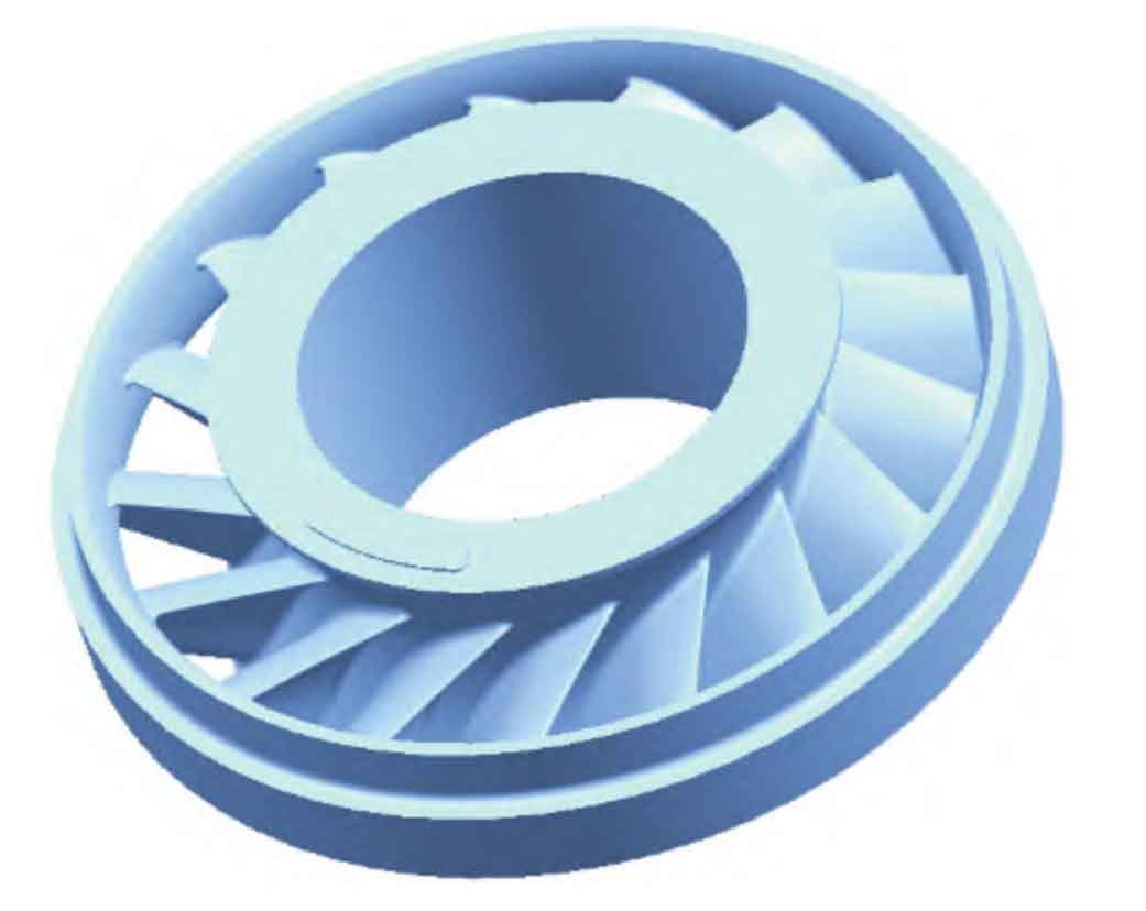
The stator’s dimensions are characterized by an overall mass of 5.3 kg, a maximum outer diameter of 274 mm, a minimum inner diameter of 122 mm, and a height of 91 mm. It comprises 17 blades evenly distributed between the inner and outer rings, forming intricate hydraulic passages for fluid flow regulation. The stringent surface profile tolerance of ±0.5 mm across the fluid flow areas underscores the casting’s high precision requirements.f
3. Initial Casting Process and Challenges
The initial casting approach employed a center-gate low pressure casting system, leveraging its ability to ensure uniform filling and improved feeding during solidification. Given the stator’s intricate blade geometry, sand cores were utilized to form the complex internal structures. However, the adopted core assembly method posed significant challenges.
3.1 Initial Core Assembly Method
The initial casting process relied on a core assembly technique wherein individual sand cores for each blade were manufactured and subsequently assembled into a complete stator core. This approach, though effective in forming the complex blade geometry, introduced dimensional instability and excessive flash formation during the casting process.
3.2 Challenges Identified
3.2.1 Dimensional Instability
The assembled core exhibited significant dimensional variability, primarily attributed to the cumulative assembly errors between individual cores. This led to inconsistent blade dimensions, with over 60% of the castings failing to meet the strict profile tolerance requirements.
3.2.2 Excessive Flash Formation
The low pressure casting process, while ensuring complete mold filling, also facilitated aluminum penetration into minute gaps between the assembled cores. This resulted in excessive flash formation along the blade edges, significantly prolonging the post-casting finishing process.
4. Casting Process Optimization
To address the identified challenges, a comprehensive review of the casting process was undertaken, focusing on core design and assembly methodology. The introduction of an integral parting technique for the sand core emerged as a promising solution.
4.1 Integral Parting Technique
The integral parting technique aimed to eliminate the dimensional variability and excessive flash formation associated with the core assembly method. This approach involved designing a single, integral sand core for the entire stator, with each blade cored out as a single unit rather than individually manufactured cores .
4.2 Core Design and Manufacture
4.2.1 Core Box Design
The core box was designed to accommodate the intricate geometry of the integral core, ensuring precise blade profiles and smooth parting lines. Special attention was paid to the core’s draft angles and parting surfaces to facilitate easy ejection after casting.
Table 1: Core Box Design Parameters
| Parameter | Value |
|---|---|
| Maximum Dimensions | 300 mm x 300 mm x 150 mm |
| Material | Steel |
| Parting Line Clearance | 0.1 mm |
| Draft Angle | 3° |
| Ventilation Holes | 2 mm diameter, spaced 50 mm apart |
4.2.2 Core Manufacturing Process
The manufacturing process involved several steps, including core box assembly, sand ramming, core curing, and ejection. Special care was taken during the ramming process to ensure uniform sand density and avoid air entrapment.
4.3 Mold Design and Assembly
The mold design was optimized to accommodate the new integral core, with special emphasis on gating and risering systems. A bottom-gating approach was adopted to ensure smooth metal flow and minimize turbulence during filling.
Table 2: Mold Design Parameters
| Parameter | Value |
|---|---|
| Gate Type | Bottom Pouring |
| Sprue Diameter | 40 mm |
| Riser Configuration | Top and Side Risers |
| Riser Diameter | 60 mm (top), 40 mm (side) |
| Ventilation System | Chimney Vents and Overflow Wells |
5. Casting Trials and Results
Following the optimization of the core and mold designs, a series of casting trials were conducted to validate the effectiveness of the integral parting technique.
5.1 Casting Parameters
The casting trials were performed using the optimized low pressure casting setup, with the following parameters:
Table 3: Casting Parameters
| Parameter | Value |
|---|---|
| Pouring Temperature | 710°C to 720°C |
| Pressurization Pressure | 0.06 MPa |
| Holding Time | 60 seconds |
| Mold Preheat Temperature | 200°C |
5.2 Casting Results
The castings produced using the integral parting technique demonstrated marked improvements over the initial core assembly method.
5.2.1 Dimensional Stability
Dimensional inspections revealed significantly improved blade profile tolerances, with over 95% of the castings meeting the strict ±0.5 mm tolerance requirement .
5.2.2 Flash Reduction
The elimination of assembly gaps between individual cores resulted in a drastic reduction in flash formation. Post-casting finishing times were reduced from an average of 40 minutes per casting to just 5 minutes, significantly enhancing production efficiency.
6. Conclusion
The introduction of an integral parting technique for the sand core in the low pressure casting process of a complex aluminum alloy stator has proven highly effective in addressing the challenges associated with the initial core assembly method. This innovation not only improved dimensional stability but also drastically reduced flash formation and post-casting finishing times. The optimized casting process ensures consistent quality and enhances production efficiency, making it a viable solution for high-precision aluminum alloy castings with intricate geometries.