
The adoption of resin-bonded sand molding for medium to large machine tool casting production represents a critical pathway towards achieving high-quality components with reduced energy consumption, lower labor intensity, and enhanced production efficiency. Castings produced via this method are characterized by their sharp轮廓 (contours), smooth surfaces, and high dimensional accuracy. My experience in implementing and refining this process has involved extensive research into optimizing parameters, designing compatible tooling, and systematically addressing quality challenges to ensure the consistent production of superior machine tool casting components.
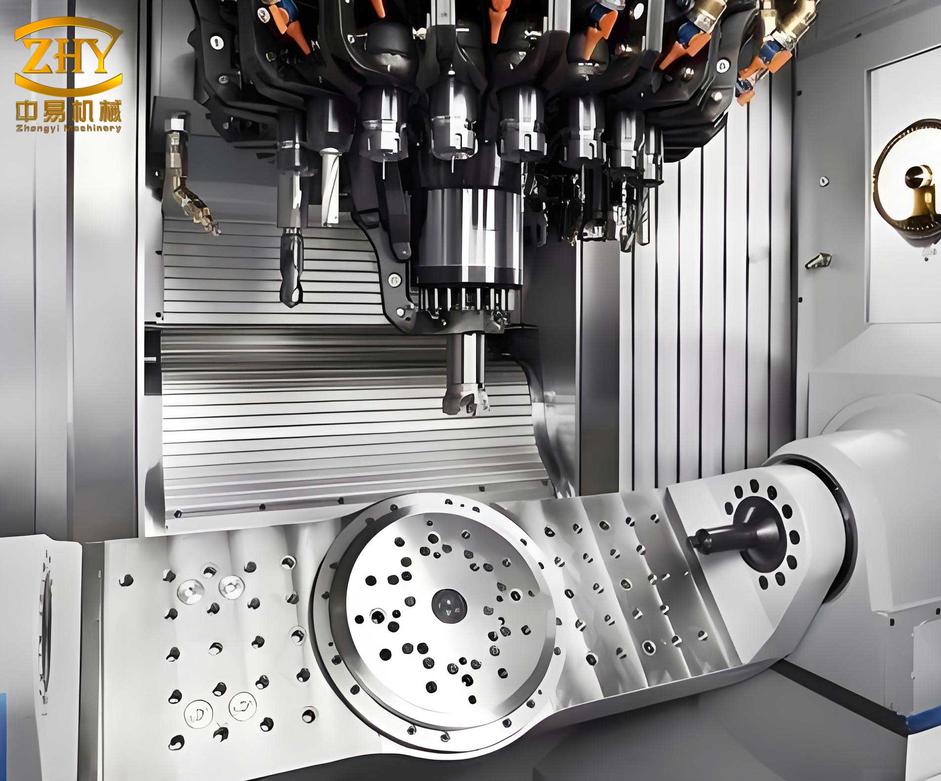
Resin Sand Process Optimization for Machine Tool Castings
Successfully adapting to the resin sand process requires a holistic review and redesign of the entire foundry methodology. The core of this adaptation lies in several key areas.
Determination of Process Parameters
Through extensive measurement and statistical analysis, the pattern allowances for resin sand molds have been established. For complex box-type machine tool casting with numerous cores that experience significant restriction during solidification shrinkage, an allowance of $$0.8\%$$ to $$1.0\%$$ is applied. For parts with less restricted shrinkage, an allowance of $$0.7\%$$ to $$0.9\%$$ is used. While resin sand molds inherently provide excellent dimensional accuracy allowing for reduced machining allowances, the slightly higher propensity for gas-related defects necessitates maintaining machining allowances similar to those used in traditional green sand practices for critical machine tool casting surfaces. The superior flatness of the mold parting line achieved with pattern plates allows for smaller joint negatives compared to green sand molding, as summarized below.
| Average Internal Box Dimension (Length + Width) / mm | Joint Negative / mm |
|---|---|
| < 1000 | 0.5 |
| 1000 – 2000 | 1.0 |
| 2000 – 3000 | 1.5 |
| > 3000 | 2.0 |
Mold wall thickness (sand backing) is minimized to the greatest extent possible without compromising mold integrity during handling or metal pouring, directly improving the sand-to-metal ratio. The camber (distortion allowance) for bed-type machine tool casting follows established norms, typically determined by the formula: Camber = (0.5 to 1.0) × L / 1000, where L is the bed length in mm.
Gating System Design and Calculation
The design of the gating system is paramount for resin sand machine tool casting quality. Two fundamental elements are the sizing of the ingates and their strategic placement.
The total cross-sectional area of the ingates is calculated using the empirical formula:
$$A_{\text{ingate}} = \frac{W}{\mu \cdot t \cdot \rho \cdot \sqrt{2gH}}$$
Where:
- $A_{\text{ingate}}$ = Total ingate area (cm²)
- $W$ = Total weight of molten metal (kg)
- $\mu$ = Flow coefficient (typically 0.45 – 0.55 for resin sand)
- $t$ = Pouring time (s)
- $\rho$ = Density of molten metal (kg/cm³)
- $g$ = Gravitational acceleration (cm/s²)
- $H$ = Effective metallostatic head (cm)
The pouring time is estimated separately using:
$$t = S \cdot \sqrt{W}$$
Where $S$ is a coefficient ranging from 1.6 to 2.0 for medium-sized iron castings.
Ingate placement is guided by principles to ensure smooth filling: avoiding excessive flow length, minimizing sharp turns in the flow path, preventing excessive dispersion of ingates, and strategically positioning them to eliminate “dead zones” or vortex formation within the mold cavity. For long bed-type machine tool casting, a well-placed runner system is preferred over a shower-type system.
Slag Trap Configuration
Strategic placement of slag traps is essential for clean metal delivery. Three types are employed:
- Pre-mold Slag Traps: Located before the ingates, these circular traps receive metal tangentially. The sudden enlargement in cross-section reduces velocity, allowing slag and gas inclusions to separate and float.
- In-mold Slag Traps: Positioned at natural “sand core” pockets or flow “dead ends” within the cavity, they collect cooler, inclusion-laden metal that loses flow momentum. Their shape is typically square or rectangular.
- Post-mold Slag Traps (Pouring Cups/End Risers): Placed at the furthest point of metal flow, these large rectangular traps collect the cooler “front-running” metal containing gases and oxides, especially useful in bed castings poured from one end.
Process Equipment and Tooling
Dedicated, segmented flasks are designed for high-volume bed-type machine tool casting to minimize sand consumption and maximize the sand-to-metal ratio. Pattern plates are standard for batch production, ensuring consistent mold quality and allowing for reduced joint negatives. Strict quality standards for wood patterns, including draft angles, geometric accuracy, structural integrity of the frame, and proper lifting devices, are enforced to leverage the high definition capability of the resin sand process.
Coatings for Resin Sand
Given the relatively poorer high-temperature performance of resin sand and the need for higher pouring temperatures in iron foundries, developing effective anti-burning-on coatings is critical. Refractory coatings based on zircon flour, high-alumina bauxite, and alcohol-based carriers have been successfully implemented. These coatings significantly enhance the resistance of molds and cores to metal penetration, effectively eliminating burn-on defects and improving the surface finish of the machine tool casting.
Process Control and Operational Discipline
Extensive experimentation has led to the establishment of an optimal sand formulation using domestic resins, catalysts, and base sand. Comprehensive work instructions cover all aspects: sand mixing (resin and catalyst ratios), molding, coremaking, coating application, and equipment operation. Furthermore, key process control points are established at the sand mixing stations, where critical parameters like resin/catalyst addition rates, tensile strength, gas evolution, pH, and loss on ignition are regularly monitored to ensure batch-to-batch consistency.
Quality of Resin Sand Machine Tool Castings
Analysis and Mitigation of Casting Defects
Two primary defects require specific attention in resin sand machine tool casting: gas porosity and burn-on/penetration.
1. Gas Porosity: Causes and Countermeasures
The high gas evolution of resin sand is a primary contributor. Measurements show a gas evolution volume of approximately $$18-22 \text{ cm}^3/g$$ at 850°C, nearly double that of green sand. Furthermore, nitrogen present in certain binders can dissociate and dissolve into the molten metal. The resulting porosity is predominantly “invasive” in nature. Theoretical analysis and practical tests, such as pouring step-cone test pieces, indicate that the key to suppression lies in rapid mold filling. A faster pouring rate and shorter pouring time ($t$) help establish metallostatic pressure quickly to counteract gas pressure at the mold-metal interface and allow more time for dissolved gases to float out before solidification.
However, excessive filling speed can trap mold gases, causing “blows” at the highest points of the cope. The balance is achieved through: increasing the number of vent holes and risers in the cope; placing slag traps in prone areas; moderately increasing pouring temperature; ensuring excellent core venting (using straw ropes or coke in large cores); and crucially, reducing mold wall thickness. As the graph in the source material illustrates, permeability decreases dramatically with increasing sand thickness. For instance, at a thickness of 50mm, permeability might be 500, but at 150mm, it can drop to 200, significantly hindering gas escape.
2. Burn-on / Metal Penetration: Causes and Countermeasures
This is primarily “mechanical penetration.” At high temperatures, the resin binder combusts and carbonizes, creating voids between sand grains. In areas of high metal velocity (e.g., near gates) or under prolonged static pressure (thick sections), molten metal can infiltrate these voids. The primary defense is the application of a high-quality, refractory coating with excellent high-temperature resistance, permeability, suspension stability, and brushability. Additionally, the use of ceramic pouring tubes or refractory bricks in high-impact areas like sprue bases and the fronts of heavy sections is highly effective.
Quality Performance Indicators
The performance of the resin sand process for machine tool casting can be quantified against several key metrics, demonstrating its superiority.
| Quality Indicator | Achieved Performance | Typical International Benchmark | Comparison |
|---|---|---|---|
| Surface Roughness (Ra) | 12.5 – 25 μm | 25 – 50 μm | Our upper limit matches the international lower limit. |
| Dimensional Tolerance (CT) | CT 11 – CT 12 | CT 12 – CT 13 | Our upper limit aligns with the international mid-range. |
| Flatness (on same mold face) | 0.3 – 0.5 mm/m | 0.5 – 1.0 mm/m | Superior flatness is consistently achieved. |
| Scrap Rate | 3 – 5% | ~5% (comprehensive) | Competitive with international standards. |
| Labor Productivity* | 80 – 100 tons/worker-year | Varies widely | Substantial improvement over previous methods. |
*Productivity calculation excludes cleaning, pattern shop, and management personnel.
Economic Benefits of the Resin Sand Process
The shift to resin sand molding for machine tool casting delivers significant and measurable economic advantages.
1. Sand Reclamation and Reuse
The implementation of sand reclamation systems allows for the recycling of spent sand. Reclamation rates of 90-95% are achievable. For an annual output of 5000 tons of castings, requiring roughly 12,500 tons of sand, this translates to reusing approximately 11,250 tons of sand annually. At a cost of $50 per ton for new silica sand, this yields an annual saving of $$\text{Saving} = 11,250 \text{ tons} \times \$50/\text{ton} = \$562,500$$.
Furthermore, reclaimed sand requires less new binder and catalyst. Resin addition can drop from 1.8% to 1.4% (relative to sand weight), with a proportional decrease in catalyst. For the same production volume, this can save an additional $100,000 annually on binding materials. Combined, these savings reduce the per-ton cost of the machine tool casting significantly.
2. Enhanced Productivity
The process integrates sand conveyance and compaction (via shooting) into a single step. Combined with pattern plate and segmented flask molding, overall productivity is greatly enhanced. Labor productivity has increased from approximately 40 tons/worker-year with previous self-setting silicate sand processes to 80-100 tons/worker-year.
3. Reduced Scrap and Rework
Through process refinements and stringent quality control, the scrap rate for machine tool casting has been drastically reduced from around 8% (with the old process) to 3-5%. The weld repair rate has dropped from 15% to below 5%. For a 5000-ton annual output, this reduction in scrap and rework can translate to annual savings in the range of $200,000 to $300,000, depending on the complexity and value of the castings.
4. Broader Societal Benefits
The high dimensional accuracy reduces “excess” metal (weight), leading to savings in raw materials, melting energy, and subsequent machining costs. The process also generates less waste sand, dust, and effluent compared to some traditional binder systems, contributing to a reduction in environmental impact.
Conclusion and Future Perspectives
The use of resin-bonded sand for medium and large machine tool casting represents a current and viable direction for advanced foundry practice. It reliably delivers the precision, surface quality, and structural integrity required for high-performance machine tools. However, challenges remain. The emission of刺激性 (irritating) gases during mixing and pouring, which are diffuse and difficult to contain, presents an ongoing environmental management challenge. Furthermore, while current coatings are effective, the quest for coatings with even higher refractoriness and superior application properties (flow-leveling) continues to drive research and development efforts. Addressing these areas will further solidify the position of resin sand molding as a leading technology for premium machine tool casting manufacture.