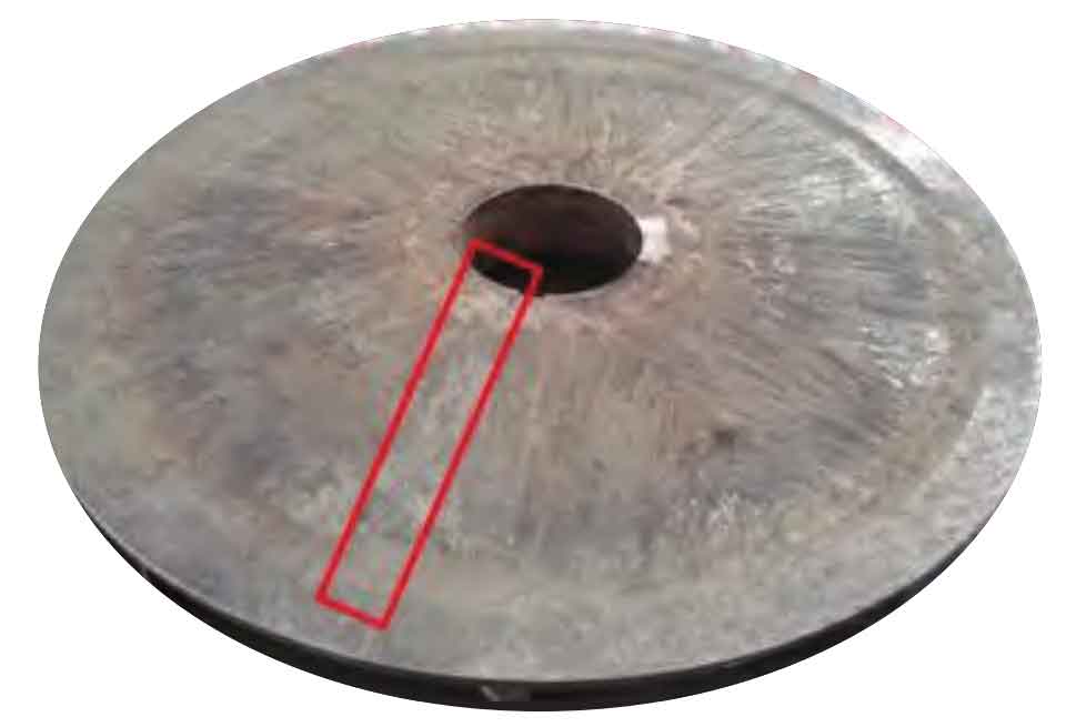
The impeller in question is made of ZTC4 titanium alloy, and its chemical composition should meet the requirements of Cast Titanium and Titanium Alloys (GB/T 15073-2014). Samples should be taken from the parts where the impeller has cracks and casting defects to detect its chemical composition. See the table for the results. It can be concluded from the test results that the chemical composition of the material meets the requirements of the standard.
| Ti(%) | Al(%) | V(%) | Fe(%) | Si(%) | C(%) | N(%) | H(%) |
| Allowance | 6.71 | 3.85 | 0.047 | 0.020 | 0.06 | 0.0060 | 0.0017 |
Macroscopic morphology
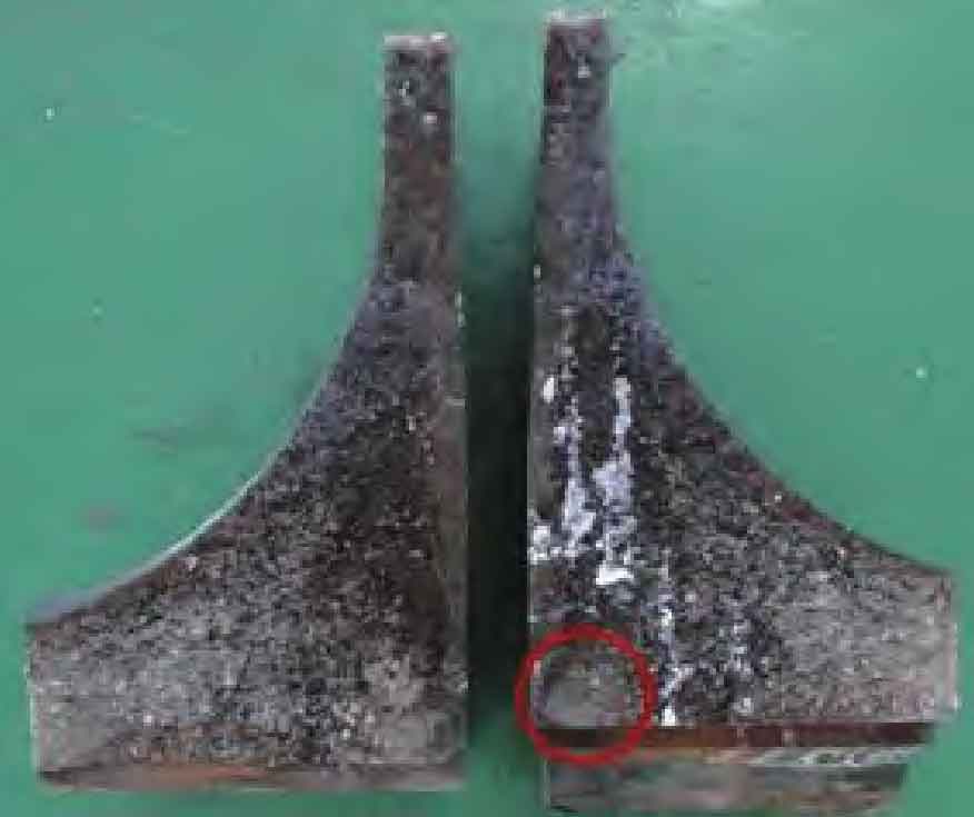
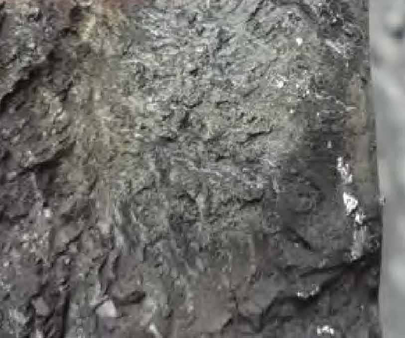
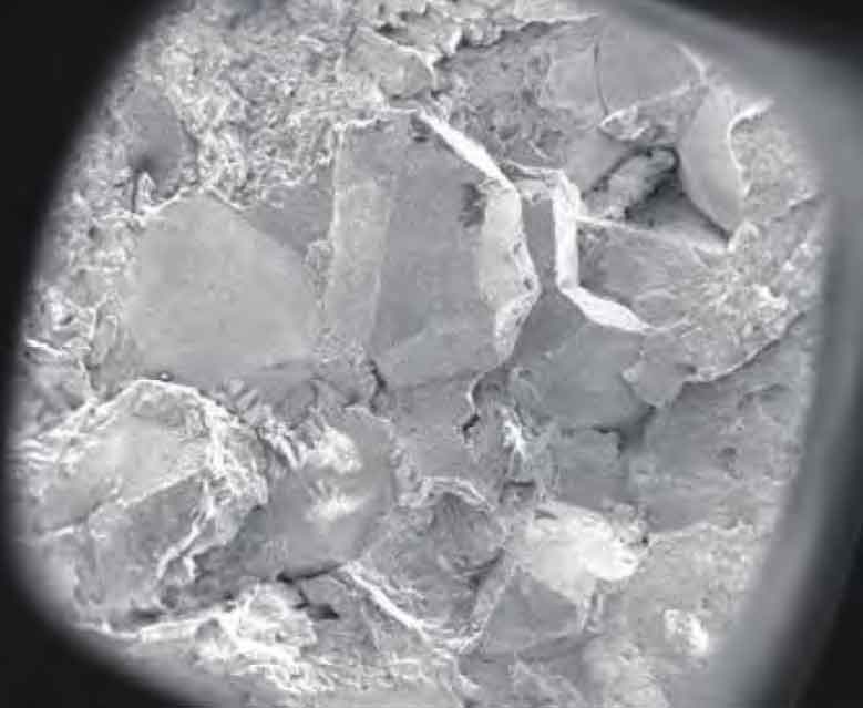
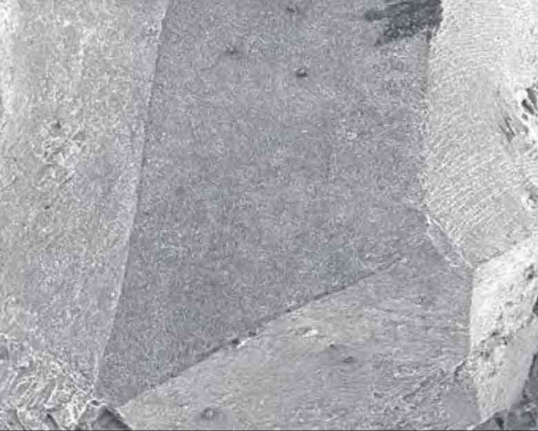
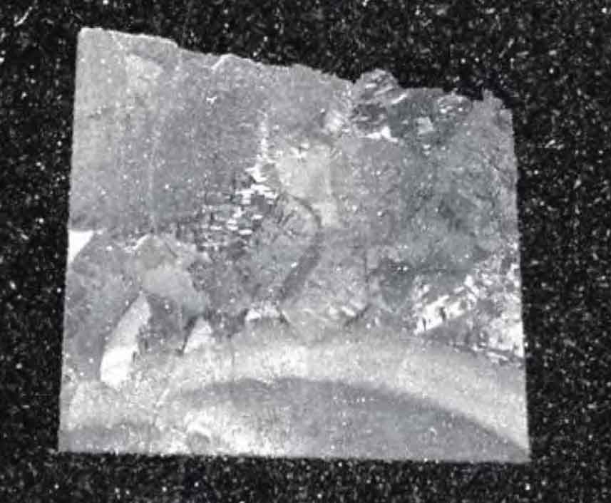
Cut the impeller crack casting defects and open the cracks, and observe the morphology of the crack casting defects as shown in Figure 1. It can be seen from Fig. 2 that the crack casting defect is characterized by intergranular cracking along the keyway of the impeller end face, with coarse grains, some of which are rough in shape, and some of the fractures near the impeller surface are black in color. The area marked by the circle is the crack source area, which is located at the stress concentration at the right angle of the impeller keyway. The port near the crack source area is relatively flat, as shown in Figure 3.
Fracture morphology
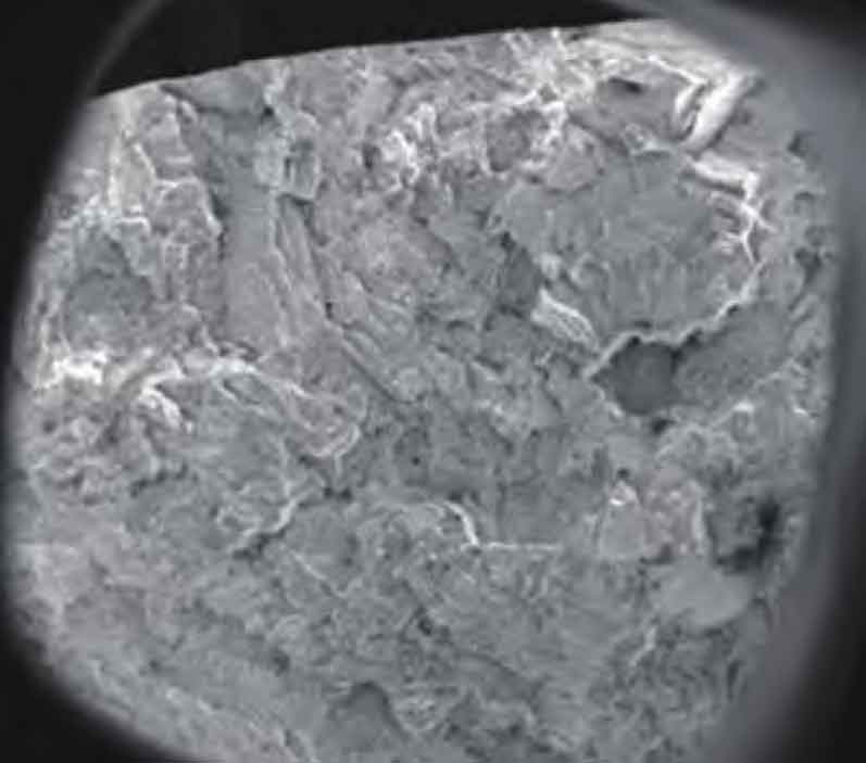
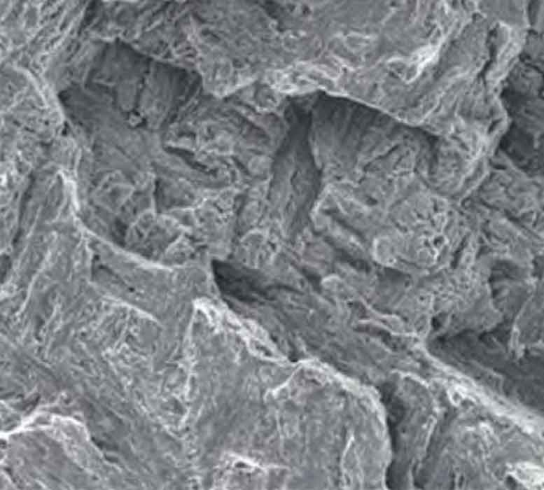
Samples were taken from the crack source area and crack propagation area of the broken part of the impeller and observed under the scanning electron microscope. The fracture morphology is cleavage fracture, as shown in Figure 4 and Figure 5. The expansion zone shows mixed fracture morphology of intergranular and cleavage, as shown in Fig. 6 and Fig. 7. The grain boundary surface presents certain toughness characteristics, as shown in Fig. 8.
Metallographic structure
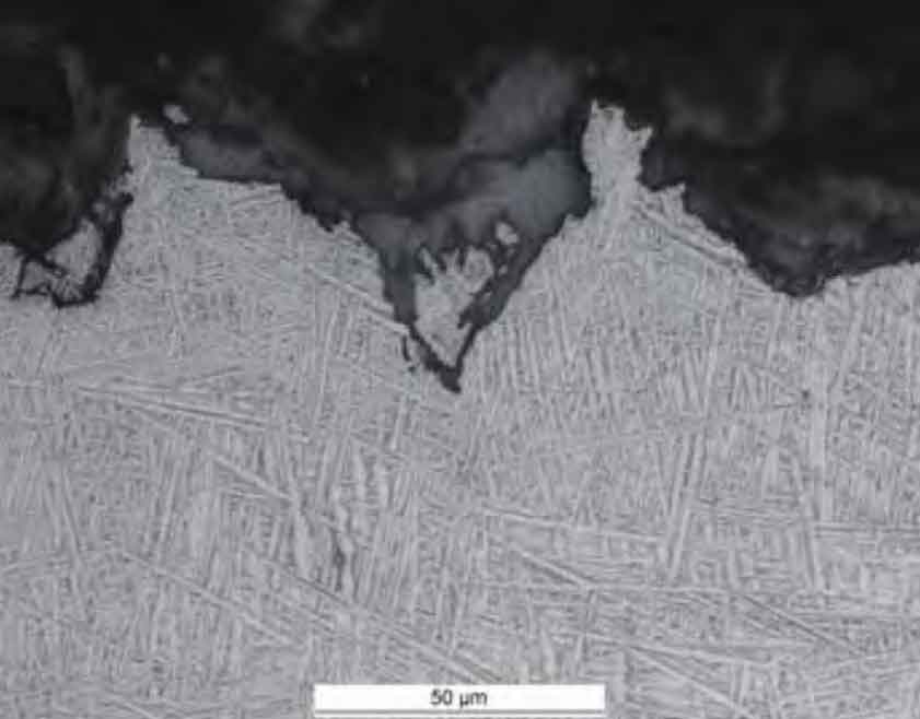
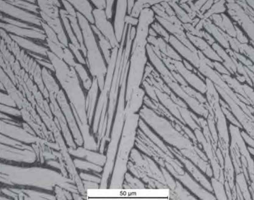
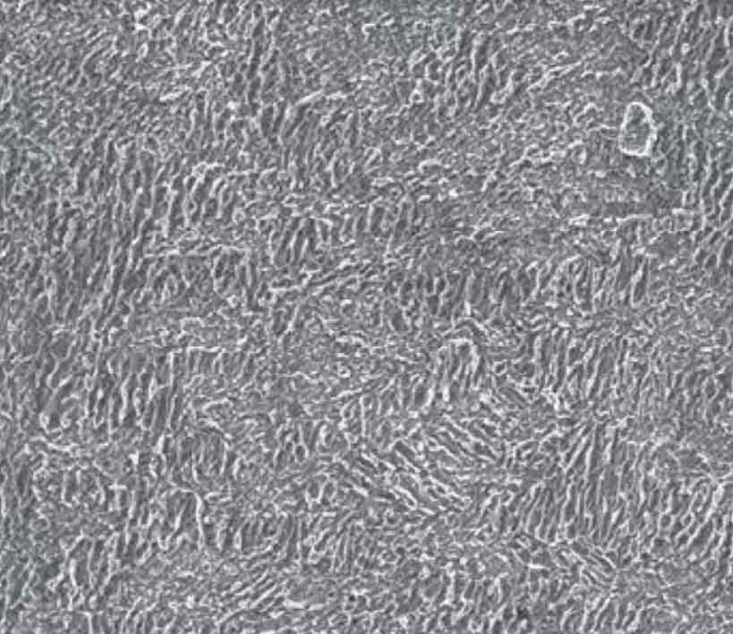
After polishing the metallographic sample at the fracture surface, it was observed that the fracture surface was uneven. The weld microstructure formed by repair welding was found at the crack source, and its morphology was as shown in Figure 9. It can be seen from Fig. 9 that oxide layer is found on the surface of the weld area, while no oxide layer is found on the fracture part of the matrix. The metallographic structure of the repair weld is lamellar α+ Intercrystalline β, As shown in Figure 10. Impeller matrix is lamellar α+ grain boundary α+ Intercrystalline β, As shown in Figure 11.

