From Figure 1, it can be seen that the upper part of the front support steel casting shaft hole is completely fractured, while the lower part is cracked but not completely fractured. Therefore, it can be determined that the entire fracture process is that the upper fracture first cracks, while the lower fracture is caused by abnormal forces after the upper fracture, which is a related fault. Therefore, the lower fracture will no longer be analyzed.

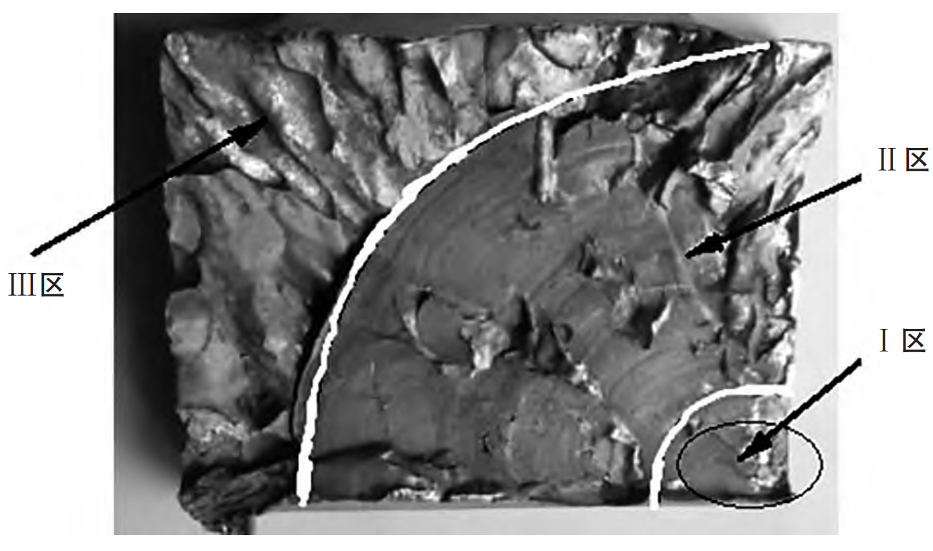
The macroscopic morphology of the fracture surface of the front support steel casting is shown in Figure 2. From the macroscopic morphology of the fracture in Figure 2, it can be seen that there is no obvious plastic deformation on this fracture, which belongs to brittle fracture. From the macroscopic morphology of the fracture surface, it can be seen that there are three very obvious fracture characteristic zones on the fracture surface. The surface of Zone I is relatively flat, smooth, and neat, with a stepped shape. The area is relatively small, and multiple fatigue crack lines can be seen, making it a multiple fatigue source area. Zone II is relatively smooth and flat, appearing as a “beach strip”. It is the trace left on the cross-section by the crack slowly expanding along the direction of force under the action of load. The area is the largest and is the expansion zone. Zone III is in the shape of rock sugar crystals, with obvious crystalline brittle fracture characteristics. The area is large and is a transient fracture zone.

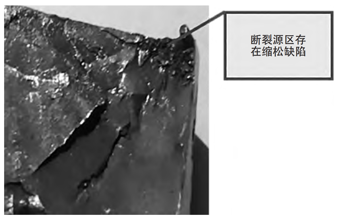
From the overall macroscopic morphology of the fracture surface, it can be seen that the fracture surface of the front support steel casting exhibits typical fatigue fracture characteristics. Under a stereomicroscope, there are still shrinkage defects in the crack source area. After analysis, it is believed that the main cause of the malfunction is the unreasonable design of the riser. For steel castings, the main function of the riser is to compensate for the liquid shrinkage of the metal in the mold cavity and the shrinkage during solidification, in order to obtain a dense steel casting without shrinkage porosity. Due to the inability of the riser position and neck size of the riser to effectively promote the sequential solidification of the steel casting, shrinkage porosity occurs in the thicker parts of the steel casting. The enlarged view of the fracture source of the front support steel casting is shown in Figure 3. To address such shrinkage defects, measures such as changing the position of the riser, improving the hook tail frame process (riser neck length size), and improving the hook body process (timely adding heating agent to the top of the riser after casting) can be taken to improve.
