
1. Gridding
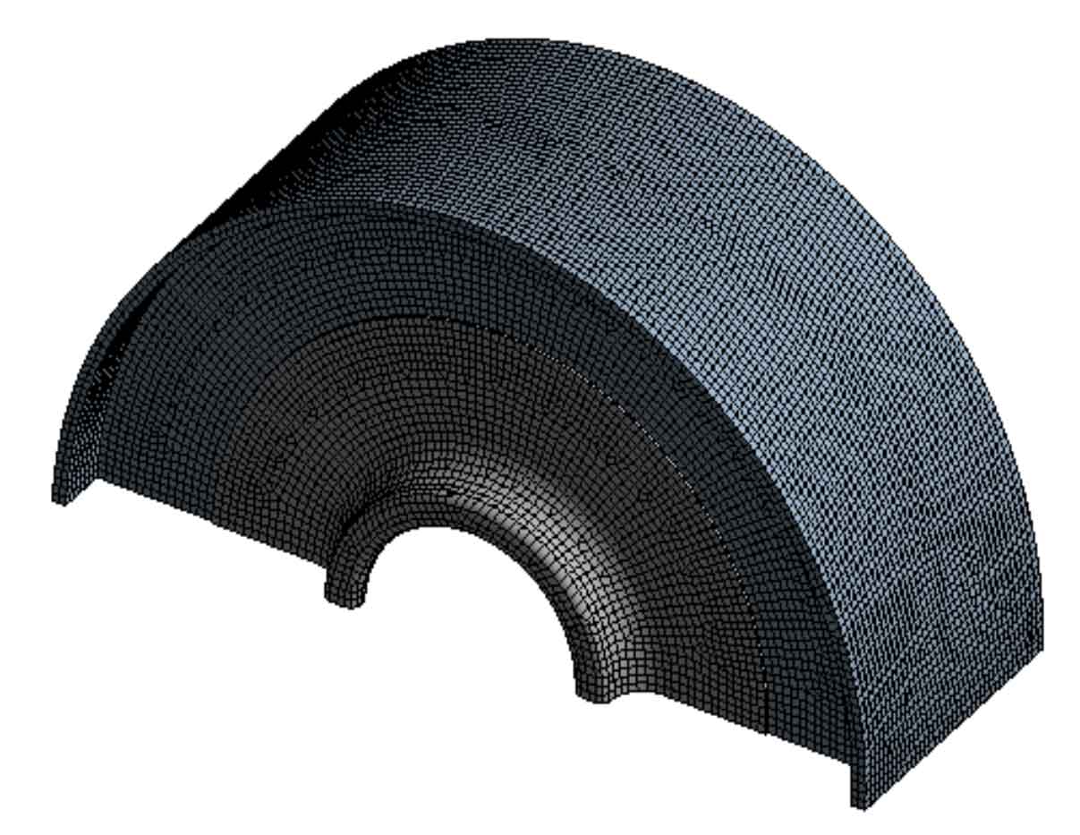
The analysis is performed in the Ansys Workbench. The first step in finite element analysis of casting diaphragm structure is to divide the grid. Here, hexahedron based method is adopted to select appropriate element size and divide the structural grid. The analysis model obtained after grid division is shown in the figure.
2. Setting Material Properties
The casting diaphragm material is ZG230-450, with tensile strength Rm=450MPa and yield limit Rel=230MPa. Elastic modulus E=2 × 10⁵MPa, Poisson’s ratio μ= 0.3, material density ρ= 7850kg/m3。
3. Setting Loads and Constraints
The load on the casting diaphragm is the pressure acting on the left and right sides of the casting diaphragm. See the table for loads under operation and venting conditions.
| Working condition | Pressure on both sides/MPa | Position of action |
| Operating conditions | 0.79/1.55 | Inlet side/outlet side |
| Venting condition | 0.79/0.13 | Inlet side/outlet side |
A friction contact is set at the contact position between the casting diaphragm and the casing, with a friction coefficient of 0.15. In the rectangular coordinate system, the vertical degree of freedom of the middle surface of the casting diaphragm is constrained. In the cylindrical coordinate system, the axial and circumferential degrees of freedom of the casing end face are constrained. For the repair weldment, binding contact is set at the contact position between the inner ring, outer ring and the original casting diaphragm.