(1) Simulation results and analysis of mold filling process
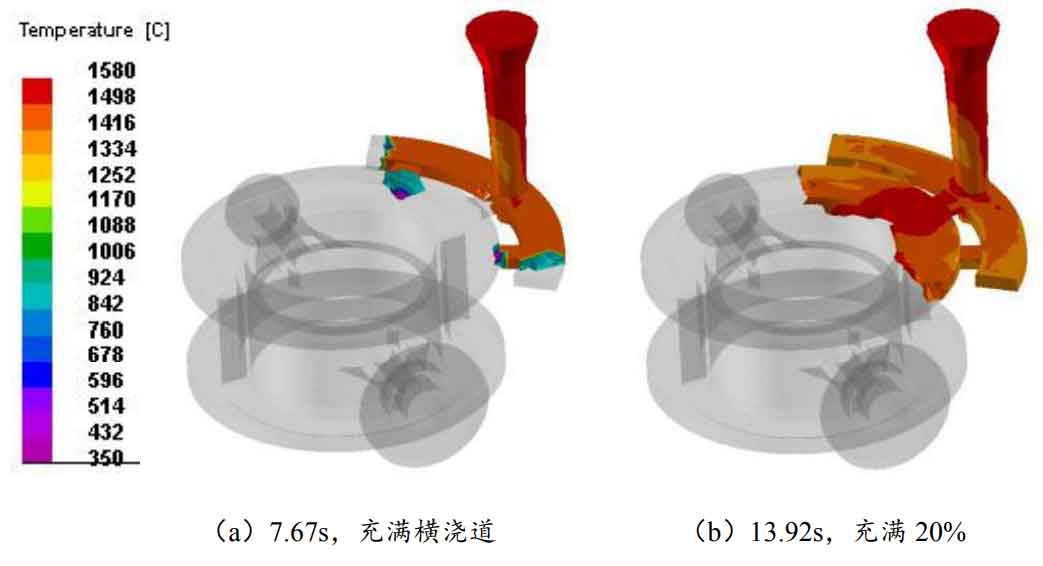
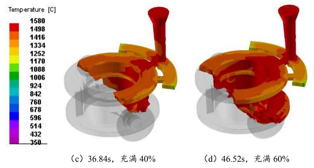
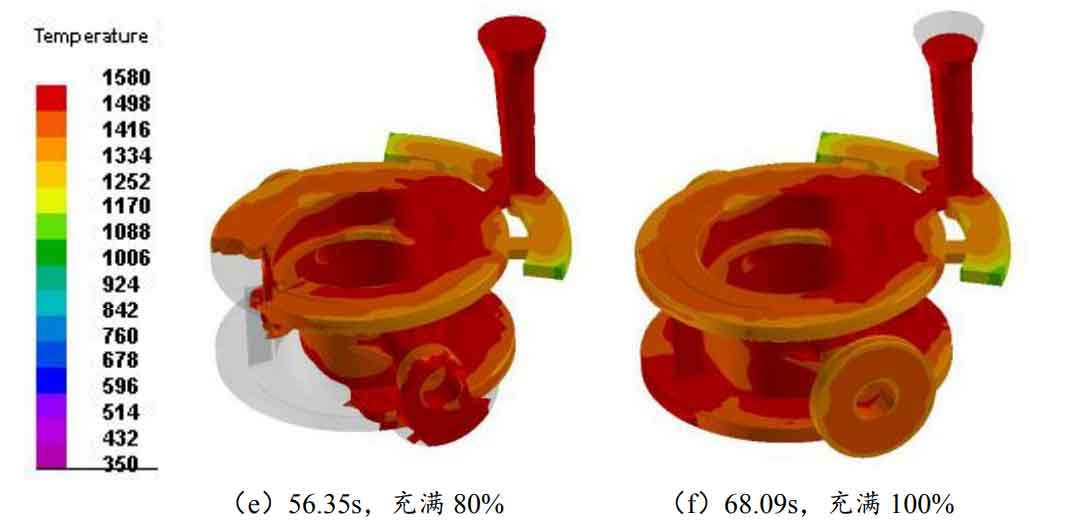
Figure 1 (a) – (f) shows the change process of mold filling temperature field of top injection type. As shown in figure a, the sprue and inner gate are filled in 7.67s. Since the sprue height of the top injection type is shorter than that of the bottom injection type, the mold filling time is shorter than that of the bottom injection type. From figures (a) – (f), it can be found that the time taken for each 20% forward mold filling is 7.67s, 13.92s, 36.84s, 46.52s, 56.35s and 68.09s. Like the filling time interval law of bottom injection type, the filling speed of liquid metal is slow first, then fast and then slow. The mold filling time of the top injection process is shorter than that of the bottom injection process. This is because the sprue height of the top injection process is shorter, the time required is shorter, the mold filling speed is faster, and the heat loss of the liquid steel in the early stage of mold filling is less, so that the liquid steel can maintain a higher temperature during the pouring process. Moreover, the mold filling direction of the metal liquid is the same as the gravity direction, and the resistance of the liquid metal flow is relatively small, It is conducive to the smooth filling of the mold cavity from top to bottom without flow interruption or retention. However, the molten metal falls from a high place and fills the mold downward, which has a large impact, and the escape direction of the pattern decomposition products is opposite. It is easy to wrap gas or residue in the molten metal.
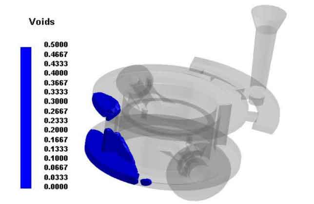
The void can be displayed on the postprocessing interface of PROCAST to reveal the disappearance of thermal decomposition of foam pattern and predict whether there is a phenomenon of wrapping. As can be seen from Fig. 2, a small piece of blue at the top of the torus represents the foam pattern, and the transparent liquid is flowing metal. When the metal liquid spreads to and everywhere, the foam pattern isolated here is surrounded by molten metal around the pyrolysis. It may exist in molten metal in solid or liquid state. If the product continues to decompose in this state, if there is no timely discharge, there will be slag inclusion and slag blowhole defect.
(2) Simulation results and analysis of solidification process
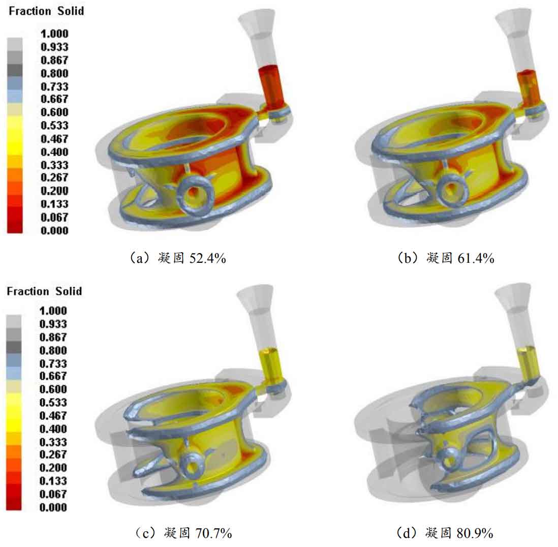
Fig. 3 shows the change and distribution of casting solid rate under the second process scheme. It can be seen from Fig. a that the liquid metal first solidifies away from the gate, and the channel between the upper and lower large torus maintains feeding for a long time. Until 80.9% solidification, the flow channel of liquid metal between the upper and lower large torus has not been disconnected, and the hot spot area of the lower torus obviously becomes smaller, A large isolated liquid phase region is formed near the gate on the upper ring surface.
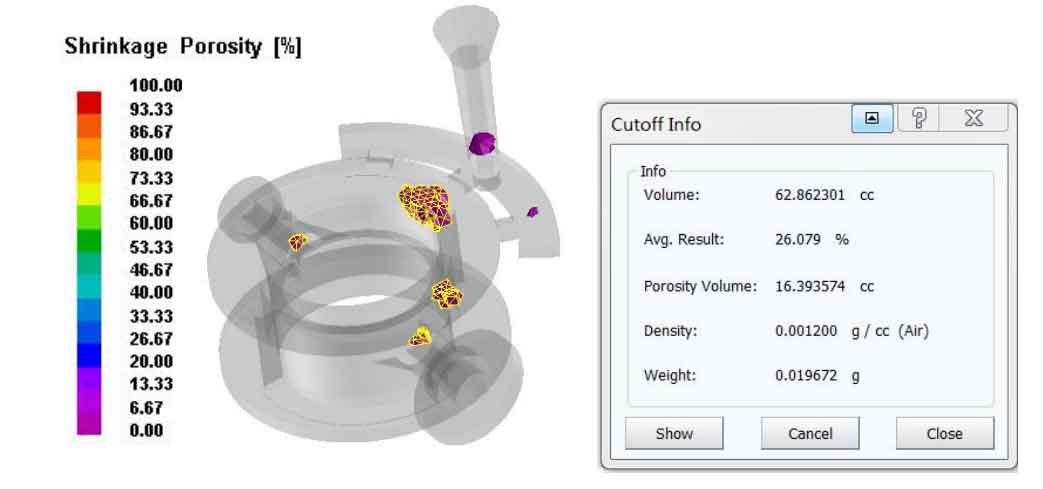
The simulated distribution of shrinkage and porosity in the top injection process scheme is shown in Figure 4. Compared with the original process scheme, the overall shrinkage and porosity distribution is not reduced, and the shrinkage rate is 26.079%.

