
Generally speaking, the layout of the injection nozzle of the casting mold has the following principles:
(1) The sand shooting range of the adjacent nozzles must have a coincident sand shooting range and cover the mold cavity completely. Generally speaking, it is related to the size, pressure and type of sand. Nozzle size and sand pressure
For the same core shooter, the pressure and the sand used are the same, so increasing the nozzle becomes the most direct and effective way to increase the area of sand shooting. But the nozzle can not be increased without limitation, because the nozzle is assembled and used together with the sand plate, rubber cup and other parts. After the nozzle size is changed, it needs to be changed together with its assembly parts. For the enterprises that need to mass produce, it is a more economical method to fix the nozzle with a certain outer diameter and select the best nozzle where it needs to be used, such as YC company The outer diameter of the nozzle is 28, 24, 20, 16, 12, 10, 8 and 7.
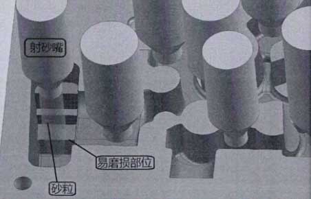
(2) In the casting mould, the cavity surface with complex shape is generally placed in the lower mould, so that the sand nozzle can be arranged more conveniently in the upper mould with relatively simple shape. In the shape of the lower mold, it is inevitable that there are some sharp or thin parts. If the sand shooting nozzle is facing the sand shooting at these parts, during the sand shooting process, the sand particles will wash these parts under the action of huge pressure, which will make these parts very easy to wear. As shown in the figure, the position easy to wear is a square core head with right angle. After the sand particles are ejected from the nozzle, they will be directly straight When the angle position is scoured for a long time, the right angle edge will be scoured into a fillet.
(3) In the deep and narrow part of the mold cavity, it is better to face the nozzle – the deep and narrow part of the mold interior. Because of the difficulty of exhaust and the limitation of the fluidity of the sand particles, it is generally the most likely part where the injection is not satisfied. If the condition is limited, the nozzle can not be directly arranged in the narrow position, but also must be arranged in the near position around it. The incomplete sand core will bring many troubles to the later sand core trimming and core assembly.
The bottom of the annular groove of the water jacket core mold is 11mm, the depth of the upper mold is 40.1mm, the depth of the lower mold is 50.1mm, and the total height of the annular groove is 90.2mm. It is determined that the nozzle must be arranged at the bottom of the annular groove to produce a full sand core. If conditions permit, the nozzle with a larger size can be selected as much as possible to increase the compactness of the sand core. Therefore, the nozzle with a diameter of 10 is designed to be used at the bottom of the annular groove, while the nozzle with a diameter of 16 is selected for the annular core head. The final nozzle arrangement is shown in the figure:
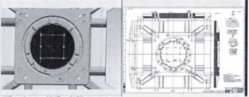
After the position of the nozzle is determined, the position of the upper top core rod is also determined, and the position of the lower top core rod of the lower mold is similar to that of the nozzle, so it is no longer praised. After the three-dimensional design of all the water jacket core molds is completed, in order to facilitate the workshop manufacturing, it is also necessary to output the three-dimensional drawings, including a series of accessories, standard parts, etc., and then mark the dimensions and prepare the process, then the mold manufacturing can be carried out in the departure room.