1. Introduction
In the field of modern manufacturing, casting technology is of great significance. Frozen sand mold casting, a new – type casting technology, has attracted increasing attention due to its green and recyclable characteristics. Different from traditional casting techniques that often use chemical binders, frozen sand mold casting uses pure water as a binder. By mixing an appropriate amount of water with fine sand and freezing it at a low temperature to form a frozen sand blank, and then processing it based on the principle of subtractive manufacturing, it realizes the rapid manufacturing of single – piece, small – batch, and complex metal parts. This technology not only reduces dust generation during the molding process but also allows the sand mold to self – collapse after pouring, without irritating odors, and the molding sand can be reused.
However, after the frozen sand mold is processed by the forming machine tool, it needs to be transported. At low temperatures, the frozen sand mold is a brittle object. Ensuring stable clamping and transportation of the frozen sand mold without damage has become a key research issue. This article focuses on studying the clamping deformation of frozen sand mold thin – walled components through a combination of experimental research and numerical simulation, aiming to optimize the clamping parameters and provide a reference for the selection of frozen sand molds and the design of fixtures.
2. Research Status of Frozen Sand Mold Technology
2.1 Technological Advantages
The frozen sand mold casting technology has several distinct advantages. In terms of environmental protection, its use of pure water as a binder significantly reduces dust generation during the molding process compared to traditional casting methods. After pouring, the sand mold can self – collapse, eliminating the need for complex sand – removal processes and reducing the generation of waste. The recyclability of the molding sand also makes it more sustainable. In the manufacturing process, it enables the rapid production of complex metal parts, which is of great value for small – batch and customized production.
2.2 Existing Research on Frozen Sand Mold
Many scholars have conducted research on various aspects of frozen sand molds. Academician Shan Zhongde proposed research plans for digital patternless composite casting equipment and intelligent green casting factories in the field of frozen sand molds. SHAN et al. studied the influence of different freezing temperatures and water contents on the tensile strength and air permeability of 100 – mesh and 200 – mesh silica sand and zircon sand frozen sand molds. Yan Qinlao et al. improved the processing efficiency of complex casting sand molds by optimizing the numerical control processing path. SHI et al. analyzed the evolution laws of the phase – field and temperature – field during the unidirectional freezing process of frozen sand molds with different pore structures through numerical simulation. YANG et al. explored the liquid – solid phase – change mechanism of binders during the additive manufacturing process of frozen sand molds and the changes in the normal temperature field and phase – change field of pre – cooled powder – bed porous media at different temperatures.
However, most of the existing research focuses on the mechanical properties such as compressive and tensile strength of frozen sand molds under different conditions, as well as the stress – strain curve from loading to failure. There is relatively little research on the optimization of elastic deformation clamping parameters when stably clamping and not damaging the frozen sand mold, which leaves room for further exploration.
3. Experimental Research on Frozen Sand Mold Clamping Deformation
3.1 Experimental Preparation
- Materials: The main materials used in the experiment include 100 – mesh silica sand, 100 – mesh zircon sand, and 100 – mesh chromite sand. These sands are commonly used in the field of casting and have different physical and mechanical properties. In addition, different contact surface materials such as rubber plates, steel plates, and polyurethane plates are selected to study their influence on the clamping deformation of frozen sand molds.
- Sample Preparation: Prepare frozen sand mold samples with different water contents. The water content (mass fraction) is set at 4%, 6%, and 8%. The samples are made into standard shapes for subsequent mechanical property testing. For example, samples for compressive strength testing are made into cubic shapes with a certain side length, and samples for friction coefficient testing are made into flat – plate shapes for easy measurement of the friction coefficient between different materials.
3.2 Experimental Measurements
- Compressive Strength Measurement:Measure the compressive strength of frozen sand molds with different water contents and sand – type materials at – 20°C. As shown in Table 1, with the increase of water content, the compressive strength of the frozen sand mold gradually increases. For silica sand, when the water content (mass fraction) is 4%, 6%, and 8%, the compressive strength is 2.187 MPa, 2.448 MPa, and 2.551 MPa respectively. This is because an appropriate increase in water content can improve the bonding force between sand grains, enhancing the overall strength of the frozen sand mold. | Sand – type Material | Water Content (Mass Fraction) | Compressive Strength (MPa) | |—|—|—| | Silica Sand | 4% | 2.187 | | Silica Sand | 6% | 2.448 | | Silica Sand | 8% | 2.551 | | Zircon Sand | 4% | 2.429 | | Chromite Sand | 4% | – |
- Friction Coefficient Measurement:Measure the friction coefficient between the outer surface of the frozen sand mold and different contact surface materials. When the water content of silica sand (mass fraction) is 6%, the friction coefficients with rubber plates, steel plates, and polyurethane plates are 0.563, 0.322, and 0.397 respectively. As shown in Table 2, it can be seen that the friction coefficient of silica – sand – based frozen sand molds with different contact surfaces is different, and this difference will affect the clamping process of the frozen sand mold. | Sand – type Material | Water Content (Mass Fraction) | Contact Surface Material | Friction Coefficient | |—|—|—|—| | Silica Sand | 6% | Rubber Plate | 0.563 | | Silica Sand | 6% | Steel Plate | 0.322 | | Silica Sand | 6% | Polyurethane Plate | 0.397 |
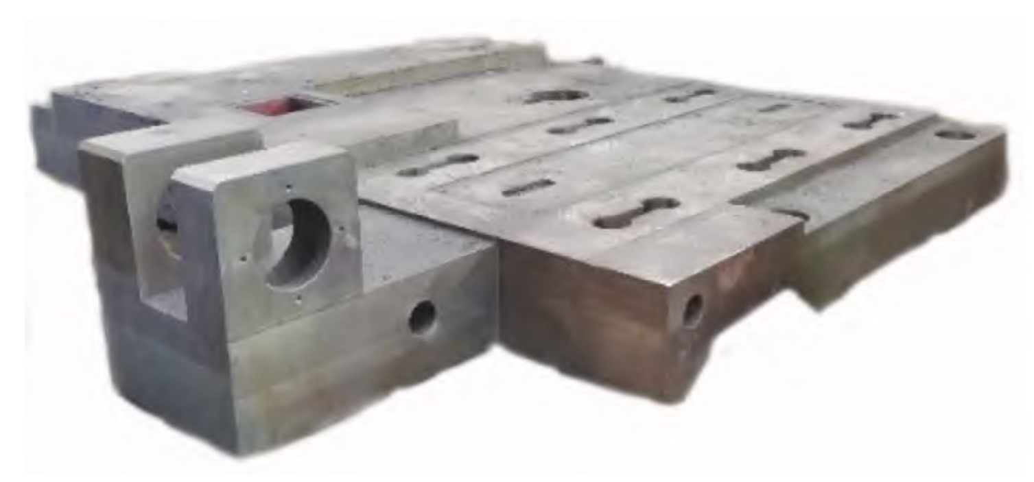
- Selection of Frozen Sand Mold Typical Parts: Select a frozen sand mold typical part with a regular internal structure, as shown in Figure 1. The size of the part is 400mm×400mm×100mm, and the wall thicknesses studied are 10mm, 20mm, 30mm, 40mm, and 50mm. The grid – division model of the part is established, and the grid size is 5mm, which is convenient for subsequent numerical simulation analysis. [Insert Figure 1: Frozen sand mold typical part and its grid – division model]
3.3 Clamping Experiment Scheme
- Clamping Principle: According to Hooke’s law, before the brittle material exceeds its proportional limit and the plastic material reaches its yield limit, it can be approximately regarded as a completely elastic body. In the process of clamping the frozen sand mold, a safety factor of 1.2 is taken to ensure the reliability of clamping. When \(F_{f}\geq G\), the frozen sand mold can be clamped. Here, \(F_{f}\) is the clamping force, and G is the weight of the frozen sand mold.
- Experimental Operation: In the experiment, use a special frozen – sand – mold fixture to perform the clamping operation. The fixture is designed to ensure that the frozen sand mold is evenly stressed on both sides during the clamping process. Apply the load as shown in Figure 2, and conduct the clamping operation along the load – applying direction to observe the deformation of the frozen sand mold during the clamping process. [Insert Figure 2: Schematic diagram of the load – clamping direction]
4. Theoretical Analysis of Frozen Sand Mold Stress
4.1 Three – Dimensional Mathematical Model of Frozen Sand Mold Force Balance
- Stress – Strain Relationship: At – 20°C, the frozen sand mold is a brittle object. In the case of stable clamping without damage, its stress and deformation can be described by the elastic – mechanics theory of three – dimensional objects. During the clamping process, the surface of the frozen sand mold bears uniform stress, and the internal part is subjected to the pressure or tension applied by the fixture. To maintain the internal force balance of the frozen sand mold, the internal stress and external force need to be in equilibrium. The stress and deformation degree of the frozen sand mold are directly related to the external force. Only when the external force applied to the frozen sand mold does not exceed its compressive strength, the frozen sand mold will undergo elastic deformation. When the external force disappears, the frozen sand mold will return to its original shape, and the corresponding internal stress will cause elastic deformation inside the frozen sand mold.
- Force – Balance Equation: The force – balance equations of the frozen sand mold in three – dimensional space are as follows: \(\sum F_{x}=\frac{\partial \sigma_{x}}{\partial x}+\frac{\partial \tau_{y x}}{\partial y}+\frac{\partial \tau_{x x}}{\partial z}+x = 0\) \(\sum F_{y}=\frac{\partial \tau_{x y}}{\partial x}+\frac{\partial \sigma_{y}}{\partial y}+\frac{\partial \tau_{z y}}{\partial z}+y = 0\) \(\sum F_{z}=\frac{\partial \tau_{x z}}{\partial x}+\frac{\partial \tau_{y z}}{\partial y}+\frac{\partial \sigma_{z}}{\partial z}+z = 0\) These equations can describe the force – balance state of the frozen sand mold during the clamping process.
4.2 Two – Dimensional Mathematical Model of the Frozen Sand Mold Strain Plane
- Simplification of the Strain Problem: When clamping the frozen sand mold, the axial direction is not stressed. As shown in Figure 3, taking the length direction as the z – axis, the two – end faces cannot move along the z – axis direction. Assume that the frozen sand mold is cut into many thin slices along the z – axis direction. Although the stress conditions of each slice are the same, due to the different shapes of the cast parts, the thickness of each plane is different, resulting in different strains on each plane. The stress – strain and displacement components of these frozen sand mold slices in the xoy plane can be regarded as functions of x and y, and have nothing to do with the z – coordinate. Therefore, it can be approximately considered that the axial displacement \(w = 0\) at each point on any cross – section of the frozen sand mold. The three – strain components \(\varepsilon_{x}\), \(\varepsilon_{y}\), and \(\gamma_{s}\) parallel to the xoy coordinate plane only change within the cross – section. In this way, the three – dimensional strain problem of clamping the frozen sand mold can be transformed into a two – dimensional plane – strain problem, which is convenient for analyzing the situation where the strain of the frozen sand mold is the largest under different conditions. [Insert Figure 3: 2D force diagram of thin – walled components in a frozen sand mold]
- Equations of the Two – Dimensional Model:
- Equilibrium equations: \(\frac{\partial \sigma_{x}}{\partial x}+\frac{\partial \tau_{y x}}{\partial y}+x = 0\), \(\frac{\partial \tau_{x y}}{\partial x}+\frac{\partial \sigma_{y}}{\partial y}+y = 0\)
- Geometric equations: \(\varepsilon_{x}=\frac{\partial u}{\partial x}\), \(\varepsilon_{y}=\frac{\partial v}{\partial y}\), \(\gamma_{x y}=\frac{\partial u}{\partial y}+\frac{\partial v}{\partial x}\)
- Physical model: \(\varepsilon_{x}=\frac{1 – \mu^{2}}{E}(\sigma_{x}-\frac{\mu}{1 – \mu}\sigma_{y})\), \(\varepsilon_{y}=\frac{1 – \mu^{2}}{E}(\sigma_{y}-\frac{\mu}{1 – \mu}\sigma_{x})\), \(\gamma_{x y}=\frac{2(1 + \mu)}{E}\tau_{x y}\)
4.3 Compressive Constitutive Relationship of Frozen Sand Mold
- Elastic – Deformation Mechanism: In engineering, the frozen sand mold and some materials (such as frozen soil, rock, and concrete) show reversible deformation characteristics within the small – deformation range, that is, they can return to their original state after unloading. The microscopic mechanism of elastic deformation is that under the action of force, the distance between microscopic particles of the object changes, but its microscopic structure remains unchanged. When the force is unloaded, the interaction force between microscopic particles will make them return to the initial state. Therefore, elastic deformation is only related to the magnitude of the load, and there is a one – to – one correspondence between stress and strain.
- Constitutive – Equation Definition: The following model is used to define the constitutive equation of the elastic stage of the frozen sand mold under compression at low temperatures: \(\left\{\begin{array}{l}\sigma<\sigma_{s}\\ \sigma = E\varepsilon_{e}\\ \sigma_{s}=\sigma_{0}-KV_{p}\\ \varepsilon=\frac{V}{L}=\varepsilon_{e}+\frac{V_{p}}{L}\end{array}\right.\) where \(\sigma_{s}\) and \(V_{P}\) are the strength and plastic – deformation amount of the sand – grain micro – element in the current state; \(\sigma_{0}\) is the strength limit in the initial state or when \(V_{P}=0\); \(\varepsilon\) and \(\varepsilon_{e}\) are the apparent strain and elastic strain respectively, and V is the compression – deformation amount; L is the length of the sand – grain micro – element. According to the established constitutive model, at a low temperature of – 20°C, for frozen sand molds with water contents (mass fraction) of 4%, 6%, and 8%, made of silica sand, zircon sand, and chromite sand, and with rubber, polyurethane, and steel – plate contact surfaces, finite – element simulation analysis is carried out on the frozen sand mold by applying different compressive stresses. The parameter values of the compressive constitutive model of the frozen sand mold are shown in Table 3. | Frozen Sand Mold | Temperature \(T(^{\circ}C)\) | Compressive Strength \(\sigma_{bc}(MPa)\) | Elastic Modulus \(E(MPa)\) | Sand – Grain Size (Mesh) | Density \((g\cdot cm^{-3})\) | Poisson’s Ratio \(\mu\) | |—|—|—|—|—|—|—| | Silica Sand (Water Content 4%) | – 20 | 2.187 | 122.15 | 100 | 2.44 | 0.211 | | Silica Sand (Water Content 6%) | – 20 | 2.448 | 123.23 | 100 | 2.34 | 0.232 | | Silica Sand (Water Content 8%) | – 20 | 2.551 | 124.13 | 100 | 2.30 | 0.241 | | Zircon Sand (Water Content 4%) | – 20 | 2.429 | 126.21 | 100 | 4.09 | 0.252 | | Chromite Sand (Water Content 4%) | – 20 | – | – | 100 | – | – |
5. Numerical Simulation of Clamping Deformation of Frozen Sand Mold Thin – walled Components
5.1 Simulation Method and Software
The finite – element method is used for numerical simulation. Software such as ANSYS is selected to establish the numerical model of the frozen sand mold. According to the experimental parameters, the material properties, geometric model, and load conditions of the frozen sand mold are input into the software. The grid – division of the model is carried out according to the established grid – division model of the frozen sand mold typical part, and the appropriate analysis type and solution method are selected to simulate the clamping process of the frozen sand mold and obtain the stress and strain distribution of the frozen sand mold during the clamping process.
5.2 Analysis of Clamping Deformation of Frozen Sand Molds with Different Wall Thicknesses under Different Water Contents
- Simulation Experiment: Conduct simulation experiments on frozen sand molds with different water contents. The water contents (mass fraction) of the frozen sand molds are set at 4%, 6%, and 8%, the material is 100 – mesh silica sand, and the contact – surface material of the clamping plate is a steel plate. Use the above – mentioned experimental parameters to perform simulation clamping and analysis on frozen sand molds with different wall thicknesses through numerical simulation methods.
- Analysis of Results: As shown in Figure 4, when clamping the silica – sand frozen sand mold with a water content (mass fraction) of 4%, in the clamping process, when the wall thickness is 40mm, the compressive stress is 0.073699 MPa, which is less than the compressive strength, and the frozen sand mold is stably clamped without damage. However, the frozen sand mold undergoes a certain amount of elastic deformation. When the wall thickness is 40mm, the strain at the easily – deformed part of the frozen sand mold is smaller than that of other wall – thickness cases. The maximum elastic strain generated at the easily – deformed thin – wall part is 0.00060409. Similarly, for the silica – sand frozen sand mold with a water content (mass fraction) of 6%, when the wall thickness is 40mm, the maximum elastic strain at the easily – deformed part is 0.00063091; for the silica – sand frozen sand mold with a water content (mass fraction) of 8%, when the wall thickness is 40mm, the minimum elastic strain at the easily – deformed part is 0.00064367. The data is summarized in Table 4.
5.3 Analysis of Clamping Deformation of Frozen Sand Molds with Different Wall Thicknesses Made of Different Materials
- Simulation Experiment: Conduct simulation experiments on frozen sand molds made of different materials. It is known from the previous section that when the water content (mass fraction) of the frozen sand mold is 4%, the elastic deformation at the most easily deformed part is the smallest. By using the method of controlling variables, select the water content (mass fraction) of the sand mold as 4%, the sand mold materials as 100 – mesh zircon sand and 100 – mesh chromite sand respectively, and the contact surface material of the clamping plate as a steel plate. Perform simulation analysis on frozen sand molds with different wall thicknesses.
- Analysis of Results: During the clamping process, when the wall thickness is 40mm, the compressive stresses of the frozen sand molds made of 4% zircon sand and 4% chromite sand are 0.10998MPa and 0.11831MPa respectively, which are less than their compressive strengths and no damage occurs. As shown in Figure 5(a), when the frozen sand mold made of 4% zircon sand with a wall thickness of 40mm is stably clamped, the strain at the easily – deformed part is less than that of other wall – thickness cases, and the maximum strain is 0.00087287. As shown in Figure 5(b), when the frozen sand mold made of 4% chromite sand with a wall thickness of 40mm is clamped, the maximum elastic strain at the easily – deformed part is 0.00091713. The data is presented in Table 5.
[Insert Figure 5: Elastic strain of frozen sand molds with a water content (mass fraction) of 4% made of different materials]
| Sand – type Material | Wall Thickness (mm) | Compressive Stress (MPa) | Maximum Elastic Strain at the Easily – deformed Part |
|—|—|—|—|
| Zircon Sand | 40 | 0.10998 | 0.00087287 |
| Chromite Sand | 40 | 0.11831 | 0.00091713 |
5.4 Analysis of Clamping Deformation of Frozen Sand Molds with Different Wall Thicknesses under Different Contact Surfaces
- Simulation Experiment: Conduct simulation experiments on frozen sand molds clamped under different contact surfaces of the clamping plate. It is known from the previous sections that when the contact surface is a steel plate, the elastic deformation at the most easily deformed part of the frozen sand mold made of 4% silica sand is the smallest. By using the method of controlling variables, select the water content (mass fraction) as 4%, the sand mold material as 100 – mesh silica sand, and the contact surface materials of the clamping plate as rubber plates and polyurethane plates respectively. Perform numerical simulation and analysis on the clamping of frozen sand molds with different wall thicknesses.
- Analysis of Results: During the clamping process, the compressive stresses when the rubber plate and the polyurethane plate stably clamp the frozen sand mold are 0.0449832MPa and 0.060581MPa respectively, which are less than the compressive strength and no damage occurs. As shown in Figure 6(a), when the silica – sand frozen sand mold with a water content (mass fraction) of 4% is stably clamped by the rubber – plate surface with a wall thickness of 40mm, the maximum elastic strain at the easily – deformed part is 0.00036748. As shown in Figure 6(b), when the silica – sand frozen sand mold with a water content (mass fraction) of 4% is stably clamped by the polyurethane – plate surface with a wall thickness of 40mm, the maximum elastic strain at the easily – deformed part is 0.00049657. The data is shown in Table 6.
[Insert Figure 6: Elastic strain when different contact surfaces clamp silica – sand frozen sand molds with a water content (mass fraction) of 4%]
| Contact Surface Material | Wall Thickness (mm) | Compressive Stress (MPa) | Maximum Elastic Strain at the Easily – deformed Part |
|—|—|—|—|
| Rubber Plate | 40 | 0.0449832 | 0.00036748 |
| Polyurethane Plate | 40 | 0.060581 | 0.00049657 |
6. Conclusion
- Friction Coefficient: When the water content of the frozen sand mold is the same, the friction coefficient between the frozen sand mold made of silica sand and different contact surfaces is smaller than that of the frozen sand molds made of zircon sand and chromite sand. This indicates that in the clamping process, the silica – sand – based frozen sand mold has less resistance with the contact surface, which is beneficial for stable clamping.
- Effect of Water Content: Under the same wall thickness, compared with clamping frozen sand molds with a water content (mass fraction) of 6% and 8%, clamping a frozen sand mold with a water content (mass fraction) of 4% produces the smallest deformation. This shows that an appropriate water content can optimize the mechanical properties of the frozen sand mold during the clamping process, reducing the risk of deformation.
- Effect of Sand – type Material and Contact Surface: Under the same wall thickness, compared with clamping frozen sand molds made of zircon sand and chromite sand, clamping a frozen sand mold made of silica sand produces the smallest deformation. And compared with using a polyurethane plate and a steel plate as the contact surface to clamp the frozen sand mold, using a rubber – plate surface to clamp the frozen sand mold produces the smallest deformation. This provides a reference for the selection of materials in the actual production process. When choosing a sand – type material and a contact – surface material for the frozen sand mold, considering these factors can effectively reduce the clamping deformation of the frozen sand mold.
7. Outlook
This research has achieved certain results in the study of the clamping deformation of frozen sand mold thin – walled components. However, there is still room for further improvement. In future research, more complex shapes of frozen sand mold parts can be considered, and the influence of factors such as different freezing rates and post – treatment processes on the clamping deformation of frozen sand molds can be studied. In addition, the combination of experimental research and numerical simulation can be further optimized to improve the accuracy of research results. By continuously exploring and researching, it is expected to provide more comprehensive and accurate theoretical support and technical guidance for the development of frozen sand mold casting technology.