
The casting industry, a cornerstone of modern manufacturing, is fundamentally transforming through the integration of computer simulation technologies. Numerical simulation of the casting process represents a critical intersection of information science, materials science, engineering mechanics, and computer graphics. By enabling the virtual observation of metal filling and solidification, this technology empowers engineers to predict and analyze potential defects such as shrinkage porosity, hot tears, and residual stresses in silico. For sand casting products, which range from simple engine blocks to complex industrial components, this capability provides a scientific basis for optimizing gating and riser systems, controlling defects, ensuring dimensional accuracy, and ultimately enhancing product quality and yield while reducing development costs and time. This article delves into the theoretical foundations, practical application workflows, and advanced stress analysis methodologies pertinent to the numerical simulation of sand casting products.
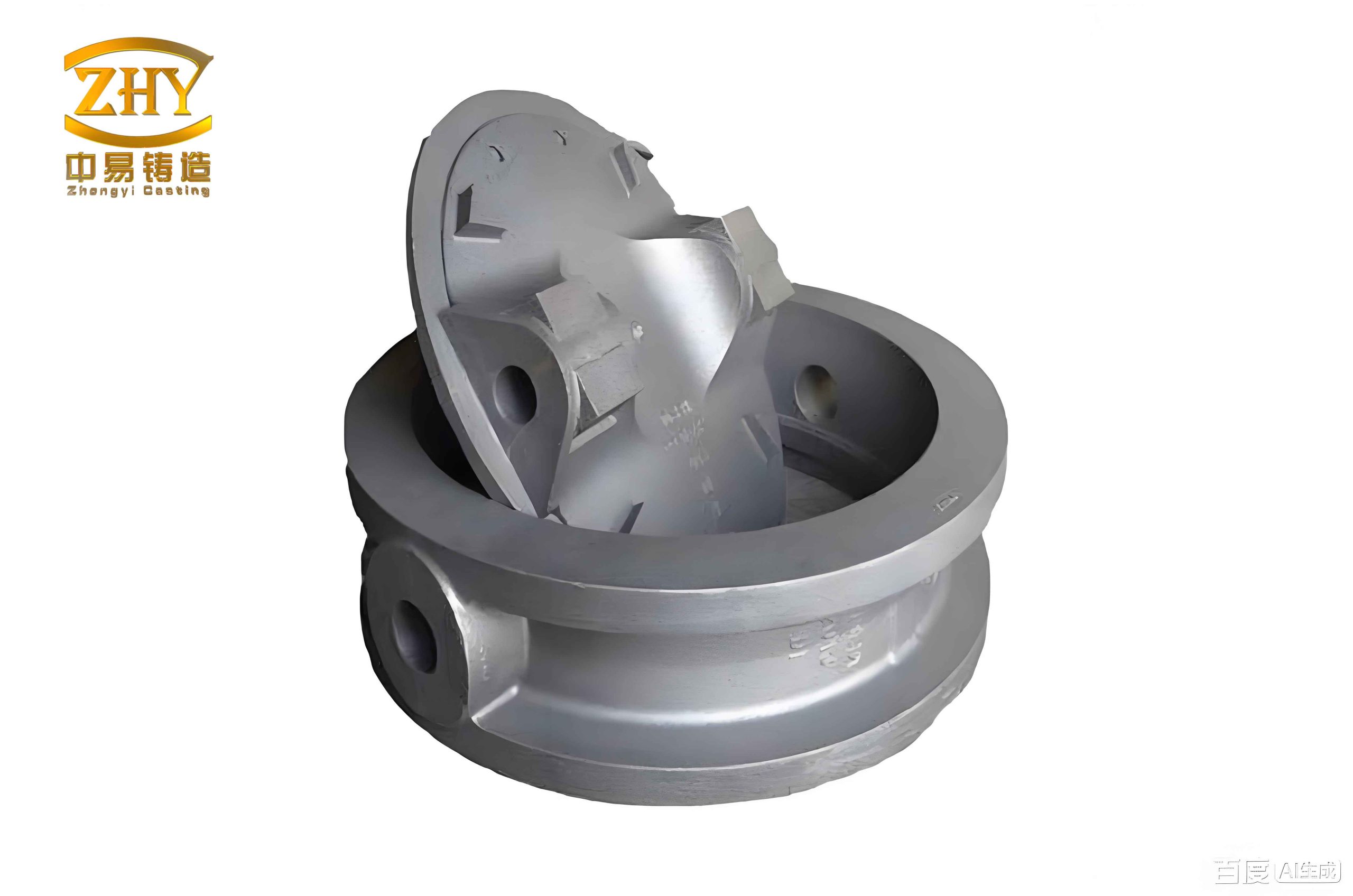
The evolution of casting simulation has progressed from simple thermal analysis to sophisticated multi-physics modeling. Initial work in the 1960s applied Finite Difference Methods (FDM) to solidification heat transfer. The 1980s saw significant advances in filling simulation with methods like the Volume of Fluid (VOF) technique for tracking free surfaces. Today, commercial software packages capable of three-dimensional, coupled fluid-flow, heat-transfer, and stress analysis are widely used. These tools allow for the virtual prototyping of sand casting products, shifting the paradigm from a costly, iterative “trial-and-error” approach to a predictive, science-based design process. The core of this technology lies in solving the fundamental governing equations of fluid dynamics and heat transfer under the complex boundary conditions of a casting process.
Theoretical Foundations for Numerical Simulation
The numerical simulation of sand casting products involves modeling several interconnected physical phenomena: the flow of molten metal during mold filling, the heat transfer during cooling and solidification, and the development of thermal stresses. Each stage requires a distinct yet coupled mathematical framework.
Filling Process Simulation
The filling stage is governed by the laws of fluid dynamics. Molten metal is typically treated as an incompressible, viscous Newtonian fluid. The core equations describing its motion are the Navier-Stokes equations, derived from the conservation of mass and momentum.
The continuity equation (mass conservation) for an incompressible flow is:
$$
\nabla \cdot \vec{u} = 0
$$
where $\vec{u}$ is the velocity vector.
The momentum conservation equation is:
$$
\rho \frac{D\vec{u}}{Dt} = -\nabla P + \mu \nabla^2 \vec{u} + \rho \vec{g}
$$
where $\rho$ is density, $P$ is pressure, $\mu$ is dynamic viscosity, and $\vec{g}$ is the gravitational acceleration vector. The energy equation, often coupled with the flow, accounts for heat transfer during filling:
$$
\rho c_p \frac{DT}{Dt} = \nabla \cdot (k \nabla T) + S
$$
where $c_p$ is specific heat, $k$ is thermal conductivity, $T$ is temperature, and $S$ is a source term (e.g., viscous dissipation). For turbulent flow, which is common in filling, Reynolds-Averaged Navier-Stokes (RANS) models with appropriate turbulence equations (like $k-\epsilon$) are employed. The free surface between the molten metal and the air in the mold cavity is tracked using methods like VOF, defined by a scalar function $F$ which satisfies:
$$
\frac{\partial F}{\partial t} + \vec{u} \cdot \nabla F = 0
$$
Solidification and Thermal Analysis
After filling, the primary focus shifts to heat transfer and phase change. The governing equation is the transient heat conduction equation with a phase change source term:
$$
\rho c_p \frac{\partial T}{\partial t} = \nabla \cdot (k \nabla T) + \rho L \frac{\partial f_s}{\partial t}
$$
where $L$ is the latent heat of fusion and $f_s$ is the solid fraction. The term $\rho L \frac{\partial f_s}{\partial t}$ represents the release of latent heat during solidification. Handling this term is crucial; the enthalpy method is commonly used, where total enthalpy $H$ is defined as:
$$
H = \int_{T_{ref}}^T \rho c_p \, dT + \rho L (1 – f_s)
$$
The relationship between solid fraction and temperature, $f_s(T)$, is essential. For many alloys, the Scheil or Brody-Flemings model is used. For example, the Scheil equation for a binary alloy is:
$$
f_s = 1 – \left( \frac{T_f – T}{T_f – T_l} \right)^{\frac{1}{k_0 – 1}}
$$
where $T_f$ is the melting point of the solvent, $T_l$ is the liquidus temperature, and $k_0$ is the equilibrium partition coefficient. Accurate prediction of defects like shrinkage porosity and macro-shrinkage cavities relies on analyzing the temperature field and solidification pattern. Criteria such as the Niyama criterion are often used to predict microporosity in steel and cast iron:
$$
G / \sqrt{\dot{T}} < C
$$
where $G$ is the temperature gradient, $\dot{T}$ is the cooling rate, and $C$ is a material-dependent constant.
Thermal Stress Analysis
The development of stress and deformation in sand casting products is due to non-uniform cooling and constraints from the mold. A thermo-elasto-plastic material model is frequently employed for stress analysis after solidification. The total strain increment $\{d\epsilon\}$ is decomposed into elastic, plastic, and thermal components:
$$
\{d\epsilon\} = \{d\epsilon^e\} + \{d\epsilon^p\} + \{d\epsilon^{th}\}
$$
The thermal strain increment is $\{d\epsilon^{th}\} = \alpha \cdot dT \{I\}$, where $\alpha$ is the coefficient of thermal expansion. The stress-strain relationship follows an incremental form based on the Prandtl-Reuss flow rule and the von Mises yield criterion. The yield function $F$ is:
$$
F = \bar{\sigma} – \sigma_y(T, \bar{\epsilon}^p)
$$
where $\bar{\sigma}$ is the von Mises equivalent stress, $\sigma_y$ is the temperature and plastic-strain-dependent yield strength. The constitutive relation can be expressed as:
$$
\{d\sigma\} = [D_{ep}] \left( \{d\epsilon\} – \{d\epsilon^{th}\} \right)
$$
where $[D_{ep}]$ is the elasto-plastic stiffness matrix, which depends on whether the material is in an elastic or plastic state. This model captures phenomena like stress reversal during cooling, as seen in stress frame castings.
Application Workflow: A Case Study on a Flywheel Casting
The practical application of simulation is best illustrated through a case study. A common sand casting product like a flywheel, made of ductile iron QT450-10, often faces challenges with shrinkage defects in its thicker sections. The traditional development cycle is resource-intensive. Implementing a simulation-led approach involves a defined workflow.
Geometry Preparation and Meshing
The first step is creating a 3D CAD model of the casting, including the gating system (pouring cup, sprue, runners, ingates) and risers. For sand casting products, the sand mold and cores must also be modeled. A crucial step is data transfer from CAD to simulation software. An effective method involves using CAD-integrated CAE tools for initial surface meshing, which is then imported into specialized casting simulation software for volume meshing. This hybrid approach ensures geometry fidelity and mesh quality. The mesh must be refined in critical areas like thin walls and near the gating system.
| Component | Material | Key Thermal Properties (Examples) |
|---|---|---|
| Casting (Flywheel) | QT450-10 | Temp.-dependent $k$, $c_p$, $\rho$, $L$, $f_s(T)$ |
| Sand Mold | Silica Sand | $k \approx 0.6 \, W/m\cdot K$, $c_p \approx 1100 \, J/kg\cdot K$ |
| Chills (if used) | Steel (H13) | High $k$ to extract heat rapidly |
Initial and Boundary Condition Setup
Accurate simulation requires defining material properties and boundary conditions. Material databases within simulation software contain temperature-dependent properties, but they often need verification or supplementation for specific alloys. Key boundary conditions include:
- Initial Temperature: Molten metal at pouring temperature (e.g., 1380°C for iron), mold at ambient temperature (e.g., 25°C).
- Interfacial Heat Transfer Coefficient (IHTC): This defines the heat exchange at the metal-mold interface. It is complex and can vary with time due to air gap formation. A typical value for sand molds might range from 500 to 1000 $W/m^2\cdot K$ initially.
- Mold External Boundaries: Convection and radiation to the environment are specified.
| Boundary Type | Condition / Coefficient | Note |
|---|---|---|
| Metal-Mold Interface | IHTC = 500 $W/m^2\cdot K$ | Simplified constant value |
| Mold-Air Interface | Convection: h=10 $W/m^2\cdot K$ Radiation Emissivity: 0.3 |
Natural convection & radiation |
Simulation, Analysis, and Optimization
With the model set up, the coupled filling and solidification analysis is run. For the initial flywheel design with multiple ingates for simultaneous filling, the simulation might reveal problematic flow patterns (turbulence, air entrapment) and, more critically, an unfavorable solidification sequence. The solidification fraction results may show that the feeding paths from the risers freeze before the thermal center of the casting, leading to isolated liquid pools and predicted shrinkage porosity, as shown by a Niyama criterion plot.
The optimization involves redesigning the feeding system based on directional solidification principles. This often means:
- Relocating or resizing risers to be adjacent to the thermal hot spots.
- Applying chills (e.g., steel blocks in the sand mold) on thicker sections to accelerate cooling and create a desired temperature gradient.
- Modifying the gating system to ensure smooth, non-turbulent filling.
A new simulation of the optimized design will show a progressive solidification front moving from the chilled areas towards the riser. The final solidified riser confirms it has performed its feeding function. The shrinkage prediction plot will show a significant reduction or elimination of defects in the casting body, with porosity confined to the riser itself. This virtual optimization process directly translates to higher quality and yield for the final sand casting product.
Advanced Stress Simulation and Software Integration
While specialized casting software excels at filling and solidification analysis, advanced, general-purpose Finite Element Analysis (FEA) software offers robust capabilities for nonlinear thermal stress analysis. A comparative study on a classic benchmark—a steel stress frame casting—illustrates the principles and highlights integration potential.
Stress Analysis of a Stress Frame Casting Using FEA
A stress frame, consisting of thick and thin sections connected, is ideal for studying stress evolution. The simulation is a sequential thermo-mechanical analysis. First, a transient thermal analysis calculates the temperature history $T(x,y,z,t)$ of the entire system (casting and sand mold). The governing energy equation is solved with appropriate boundary conditions. The thermal history reveals that the thin section cools and solidifies much faster than the thick section.
This temperature history is then applied as a thermal load in a subsequent structural analysis. The material model must account for temperature-dependent elastoplastic behavior, including the drastic drop in yield strength and elastic modulus near the solidus temperature. The von Mises stress evolution typically shows:
- Early Stage: The cooling thin section contracts but is restrained by the still-hot, mushy/thick section. The thin section develops tensile stress, while the thick section is under compression.
- Mid-Stage: The thick section begins cooling rapidly. Its desire to contract is now restrained by the already solid, cooler thin section. This causes a stress reversal: the thin section goes into compression, and the thick section develops tensile stress.
- Final Stage (Room Temperature): Residual stress patterns are locked in, with the thick section often retaining significant tensile residual stress, which is a critical consideration for the performance of the sand casting product.
The mathematical basis uses the incremental stress-strain relation with a temperature-dependent yield surface:
$$
\sigma_y(T) = \sigma_{y0} \cdot \phi(T) \quad \text{where } \phi(T) \rightarrow 0 \text{ as } T \rightarrow T_{solidus}
$$
Where $\sigma_{y0}$ is the room-temperature yield strength and $\phi(T)$ is a degradation function.
Towards an Integrated Simulation Workflow: ProCAST and ANSYS
Specialized casting software (e.g., ProCAST) and general FEA software (e.g., ANSYS) have complementary strengths. An integrated workflow is highly desirable: using ProCAST for accurate modeling of the complex filling and solidification physics to obtain a precise thermal history and residual stress field, and then transferring these results as an initial state to ANSYS for further structural analysis under service loads. The technical challenge lies in data mapping.
The connection requires two main conversion programs:
- Mesh Data Converter: Translates the node and element data from the casting simulation’s mesh format (often tetrahedral) to a format readable by the FEA software, ensuring consistent geometry definition.
- Stress/State Data Converter: This is more complex. It must extract the calculated residual stress tensor field (six components at each node: $\sigma_{xx}, \sigma_{yy}, \sigma_{zz}, \tau_{xy}, \tau_{yz}, \tau_{zx}$) from the casting simulation results. It then maps and reformats this stress field onto the FEA mesh, often requiring interpolation, and writes it in the FEA software’s format for defining an initial stress condition. This allows ANSYS to start its analysis from the “as-cast” stressed state.
The following table outlines the key aspects of this integration:
| Integration Step | Challenge | Potential Solution |
|---|---|---|
| Mesh Transfer | Different element types & numbering | Use universal format (e.g., NASTRAN .nas) or direct converter; ensure volume/face associations are preserved. |
| Stress Field Mapping | Spatial interpolation from one mesh to another; separating casting stress from mold stress. | Use shape functions of source mesh to project stresses to target mesh nodes; filter data by material ID. |
| Defining Initial State in FEA | Software-specific commands for initial stress loading. | Generate a text file with `INIS` or equivalent commands listing node/element and stress tensor values. |
Successful integration creates a powerful digital thread, enabling designers to assess not just the manufacturability of a sand casting product, but also its performance in real-world loading conditions, starting from its inherent cast-in stresses.
Summary and Future Outlook
Numerical simulation has undeniably become an indispensable tool in the design and manufacture of high-integrity sand casting products. This article has outlined the core theoretical models governing mold filling, solidification, and stress formation. The practical case study demonstrated how simulation can diagnose defects and guide the optimization of gating and feeding systems to improve quality and yield. Furthermore, the exploration of advanced thermal-stress analysis and software integration points towards a future of comprehensive, multi-stage virtual prototyping.
The future development of casting simulation will focus on several key areas:
- Enhanced Model Fidelity: Incorporating more physics, such as accurate mold distortion, advanced treatment of interfacial heat transfer (IHTC) as a function of gap formation, and the prediction of microstructural evolution (grain size, phase distribution) to directly estimate mechanical properties.
- High-Performance Computing (HPC) and AI: Leveraging parallel computing and machine learning algorithms to drastically reduce computation time for complex geometries and enable real-time simulation or automatic optimization of process parameters.
- Seamless Integration and Digital Twins: Creating robust, standardized interfaces between simulation software, CAD, and factory floor data systems. This will facilitate the creation of “digital twins” for castings, where the simulation model is continuously updated with real production data for predictive maintenance and quality control.
- Material Databases: Expanding and validating comprehensive, accessible databases of temperature-dependent thermophysical and mechanical properties for a wider range of casting alloys and mold materials.
As these advancements mature, the numerical simulation will transition from being a validation tool used by specialists to an integral, front-end design driver. It will empower engineers to conceive and verify robust manufacturing processes for even the most complex sand casting products before any metal is poured, ensuring competitiveness through higher quality, reduced costs, and accelerated time-to-market.